Rotary closed type compressor and refrigerating cycle apparatus

a compressor and refrigerating cycle technology, applied in the direction of lighting and heating apparatus, positive displacement liquid engine, liquid fuel engine, etc., can solve the problems of adversely affecting cost and complicated configuration

Active Publication Date: 2006-01-05
TOSHIBA CARRIER CORP
View PDF3 Cites 38 Cited by
  • Summary
  • Abstract
  • Description
  • Claims
  • Application Information

AI Technical Summary

Benefits of technology

[0013] A rotary closed type compressor of the present invention is configured such that an electric motor unit and a rotary compression mechanism unit coupled to the electric motor unit are housed in a closed case and the closed case is caused to be in a high-pressure state by tentatively discharging gas compressed by the compression mechanism unit into the closed case, the compression mechanism unit comprises a first cylinder and a second cylinder having cylinder chambers, respectively, an eccentric roller being housed in the cylinder chamber while being eccentrically rotatable, vanes which are provided in the first cylinder and the second cylinder, respectively, the vane bei

Problems solved by technology

Therefore, the configuration becomes comp

Method used


Image

  • Rotary closed type compressor and refrigerating cycle apparatus
  • Rotary closed type compressor and refrigerating cycle apparatus
  • Rotary closed type compressor and refrigerating cycle apparatus

Examples


first embodiment

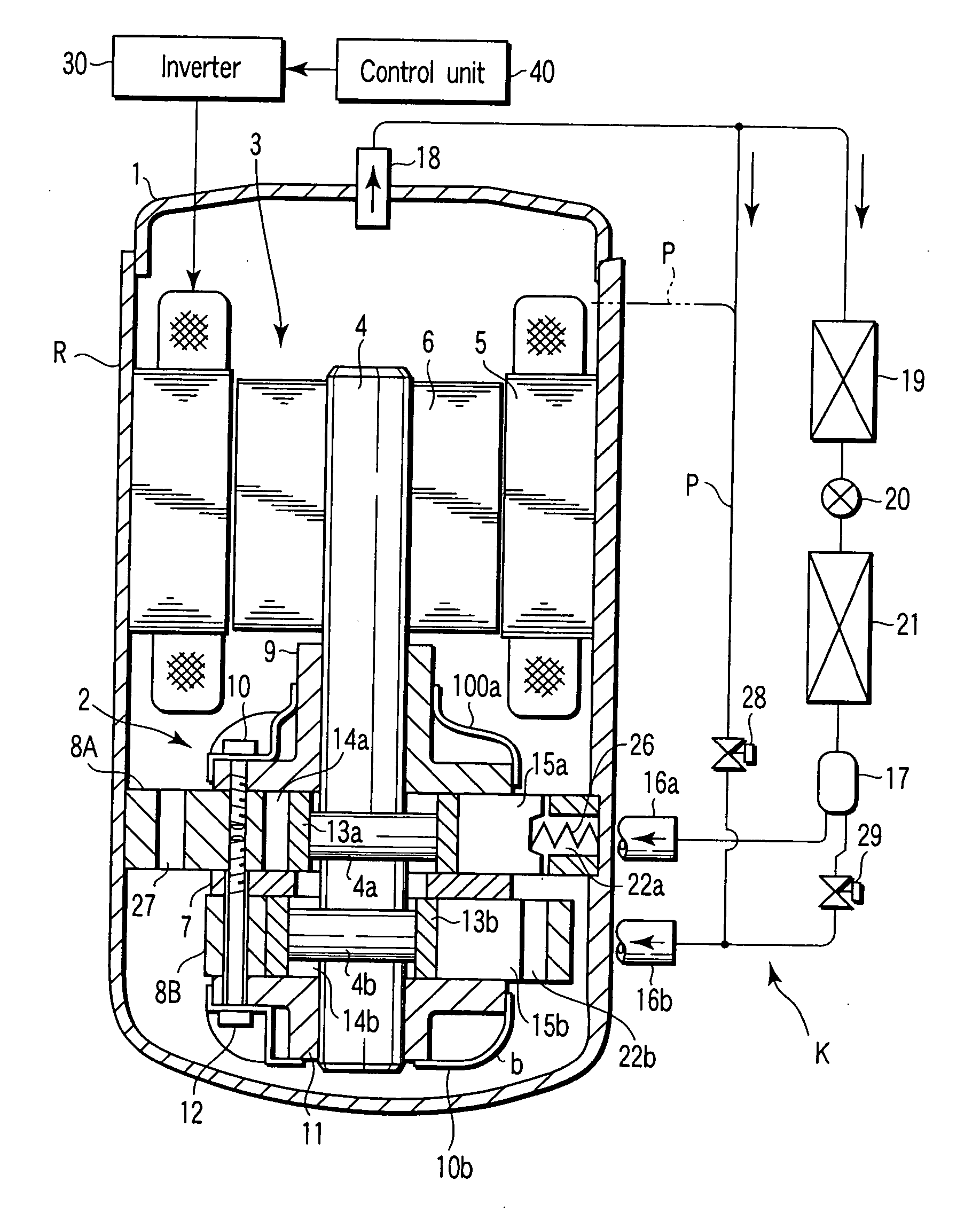
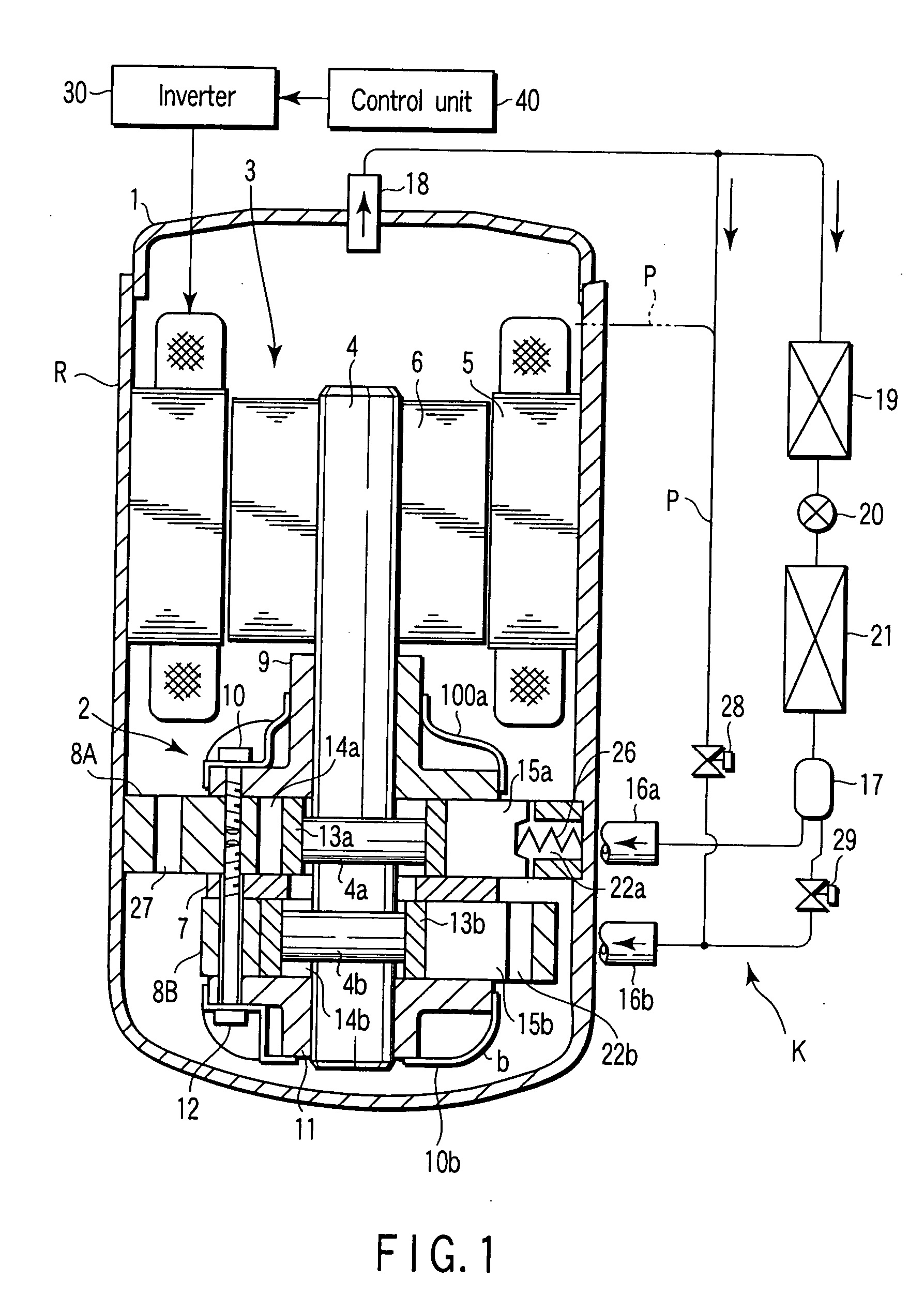
[0025] Referring now to the drawings, a first embodiment of the invention will be described below. FIG. 1 is a view showing a sectional structure of a rotary closed type compressor R and a configuration of a refrigerating cycle equipped with the rotary closed type compressor R.

[0026] First the rotary closed type compressor R will be described. Reference numeral 1 designates a closed case. A later-described compression mechanism unit 2 is provided in a lower portion of the closed case 1, and an electric motor unit 3 is provided in an upper portion of the closed case 1. The electric motor unit 3 and the compression mechanism unit 2 are coupled through a rotating shaft 4.

[0027] The electric motor unit 3 includes a stator 5 which is fixed to an inner surface of the closed case 1 and a rotor 6 which is arranged inside the stator 5 while separated from the stator 5 with a predetermined gap, the rotating shaft 4 being inserted into the rotor 6. The electric motor unit 3 is electrically c...

second embodiment

[0053]FIG. 3 is a view for explaining a configuration of a pressure switching mechanism Ka of a second embodiment. The rotary closed type compressor R and the refrigerating cycle have the same configurations as the above-described first embodiment, they are indicated by the same numerals and the descriptions will be omitted. The pressure switching mechanism Ka has the same configuration as the pressure switching mechanism K in that the branch pipe P equipped with the first on-off valve 28 is connected to a predetermined region. The pressure switching mechanism Ka has the feature in that a check valve 29A is provided instead of the second on-off valve 29. The check valve 29A permits the refrigerant to be passed from the accumulator 17 side to the second cylinder chamber 14b side, and the check valve 29A prevents the reverse flow of the refrigerant.

[0054] When the overall-capacity operation is selected, the first on-off valve 28 is closed. The low-pressure gas introduced to the sucti...

third embodiment

[0056]FIG. 4 is a view for explaining a configuration of a pressure switching mechanism Kb of a third embodiment. The rotary closed type compressor R and the refrigerating cycle have the same configurations as the above-described first embodiment, they are indicated by the same numerals and the descriptions will be omitted. The pressure switching mechanism Kb includes a three-way selector valve 35 having ports connected to the end portions of the branch pipe P which is branched from the discharge pipe 18, a guide pipe 16 which introduces and guides the low-pressure gas evaporated from the accumulator 17, and a suction pipe 16b which is communicated with the suction portion of the second cylinder chamber 14b.

[0057] When the overall-capacity operation is selected, the three-way selector valve 35 communicates the suction pipe 16 and the second cylinder chamber 14b. Therefore, the second cylinder chamber 14b becomes the low pressure, which generates the pressure difference between the ...


PUM


Abstract

A rotary closed type compressor is configured such that an inside of a case becomes high pressure, and the rotary closed type compressor comprises a first cylinder and a second cylinder having cylinder chambers in which eccentric rollers are housed, respectively, vanes which divide the cylinder chamber into two sections, respectively, and vane chambers in which back-face side end portions of the vanes are housed, respectively. The vane on the first cylinder side is pressed and biased by a spring member provided in the vane chamber, and the vane on the second cylinder side is pressed and biased according to pressure difference between case internal pressure introduced to the vane chamber and suction pressure or discharge pressure introduced to the cylinder chamber.

Description

CROSS-REFERENCE TO RELATED APPLICATIONS [0001] This is a continuation application of pct application No. PCT / JP2004 / 001884, filed Feb. 19, 2004, which was published under pct article 21(2) in Japanese. [0002] This application is based upon and claims the benefit of priority from prior Japanese Patent Applications No. 2003-074250, filed Mar. 18, 2003; and No. 2003-310482, filed Sep. 2, 2003, the entire contents of both of which are incorporated herein by reference.BACKGROUND OF THE INVENTION [0003] 1. Field of the Invention [0004] The present invention relates to a rotary closed type compressor constituting a refrigerating cycle of, for example, an air conditioner and a refrigerating cycle apparatus constituting the refrigerating cycle with the rotary closed type compressor. [0005] 2. Description of the Related Art [0006] Usually, a rotary closed type compressor has a case internal high-pressure configuration, in which an electric motor unit and a compression mechanism unit coupled t...

Claims


Application Information

Patent Timeline
IPC IPC(8): F03C2/00F04C2/00F04C23/00F04C18/356F04C28/00F04C28/06F04C29/00F04C29/12F25B1/00
CPCF04C18/3564F04C2270/56F04C28/065F04C23/008F04C18/356F04C29/00
Inventor KAWABE, ISAOMOCHIZUKI, KAZUOKITAICHI, SHOICHIROHIRANO, KOJIONODA, IZUMITAKASHIMA, KAZU
Owner TOSHIBA CARRIER CORP
Why Eureka
Try Eureka