
Electrical connector and sleeve apparatus and method of assembly

a technology of electrical connectors and sleeves, applied in the direction of electrical apparatus, line/current collector details, and permanent deformation connection, etc., can solve the problems of incorrect placement of wires and sleeves in the terminals, damage to wires secured to the terminals, and crimping of insulation sleeves at the crimp, so as to facilitate proper placement of wires in the terminals and simplify the construction of terminals

Active Publication Date: 2006-01-05
HERMETIC MOTORS LP
View PDF16 Cites 5 Cited by
  • Summary
  • Abstract
  • Description
  • Claims
  • Application Information

AI Technical Summary

Benefits of technology

[0007] The electrical connector apparatus of the present invention and its method of assembly overcome the disadvantages of prior art electrical connectors described above. The electrical connector apparatus of the invention eliminates the insulation sleeve crimp from the prior art terminal. In lieu of the sleeve connection at the terminal, the sleeve is provided with a sufficient length to allow the proximal end of the sleeve to be secured to the electrical device, i.e., the stator windings of the electrical motor. In this way, the insulation sleeve distal end is held stationary relative to the electric terminal at the opposite end of the electrical device wire. This construction of the electrical connector apparatus of the invention, and its method of assembly allows the operator assembling the connector apparatus to concentrate on the placement of the electrical device wire in the electric terminal, simplifies the construction of the terminal to facilitate proper placement of the wire in the terminal, and adds the additional protection of the insulation sleeve over the wire at the lead dwell where the wire enters the electrical device.

Problems solved by technology

However, problems have been encountered in the assembly of electrical connectors of the type disclosed in the above-referenced patent.
However, at times lead wires secured to the terminal are damaged and / or cut at the insulation sleeve crimp.
In addition, at times the lead wires and sleeve are incorrectly placed into the terminals.
Broken lead wires have also been encountered at the lead dwell of the stator casing where the lead wires enter the motor housing.
Some of the problems encountered in the use of the prior art electrical connector are attributed to the assembly of the connector.

Method used


Image

  • Electrical connector and sleeve apparatus and method of assembly
  • Electrical connector and sleeve apparatus and method of assembly
  • Electrical connector and sleeve apparatus and method of assembly

Examples


Embodiment Construction

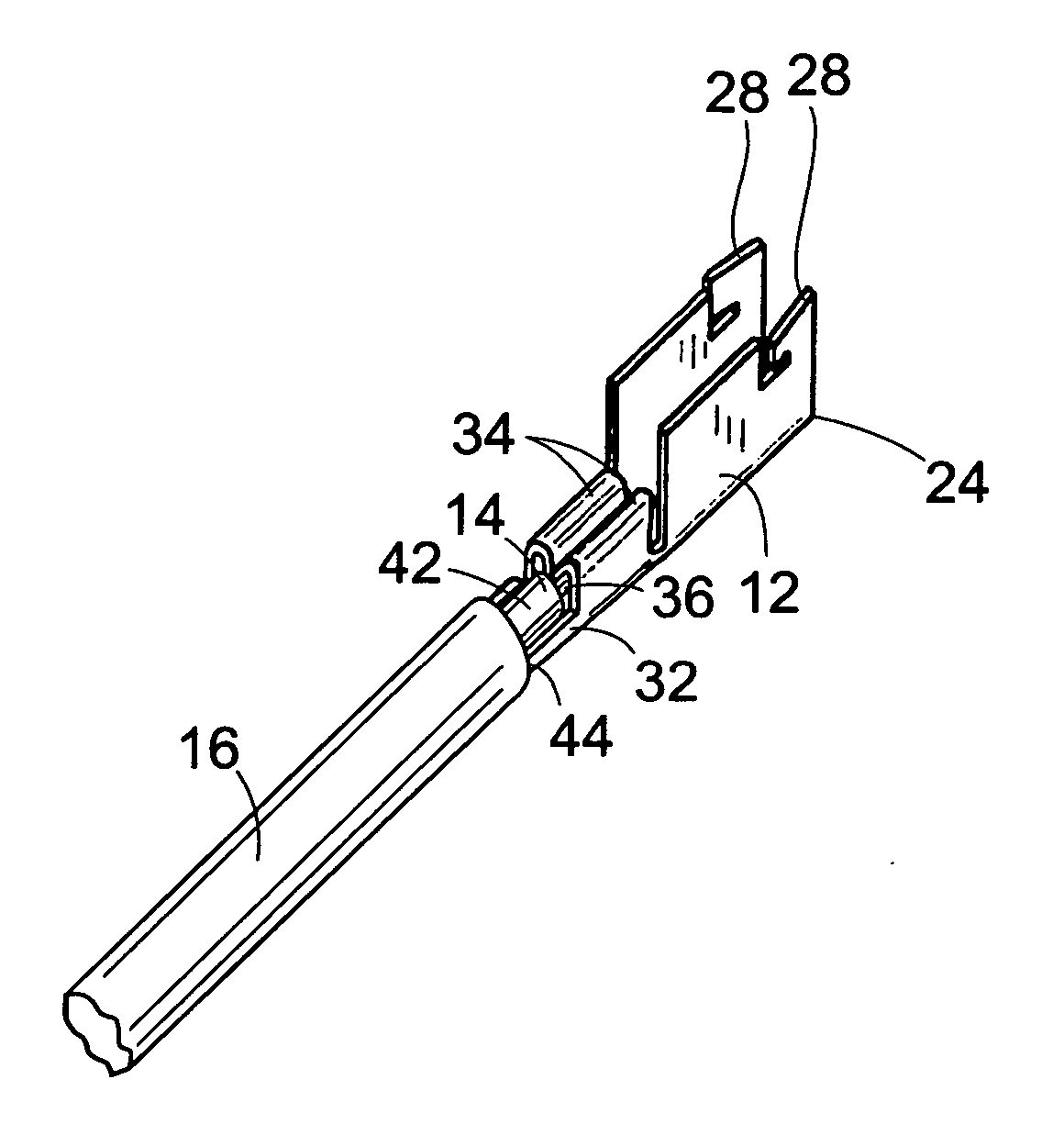
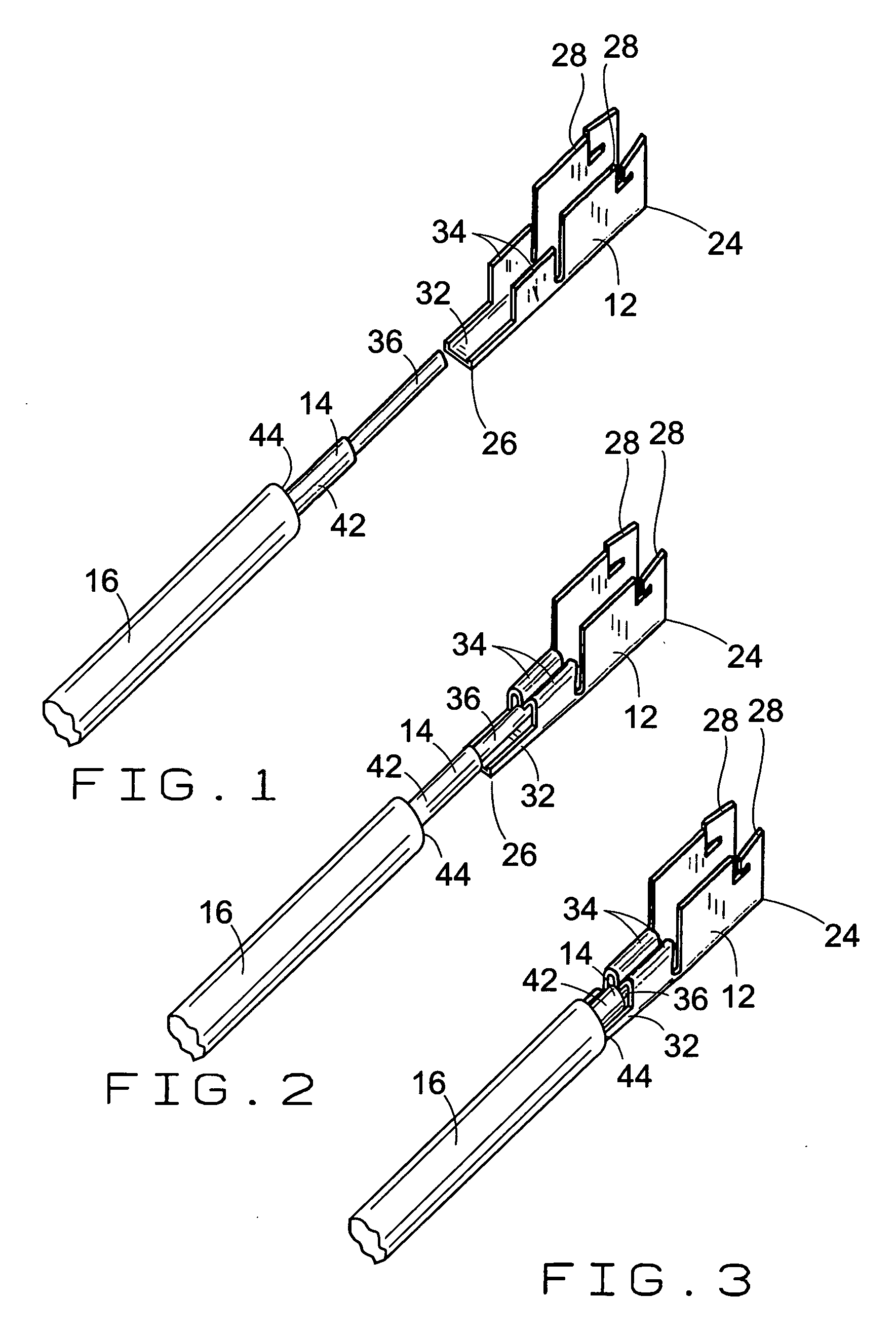
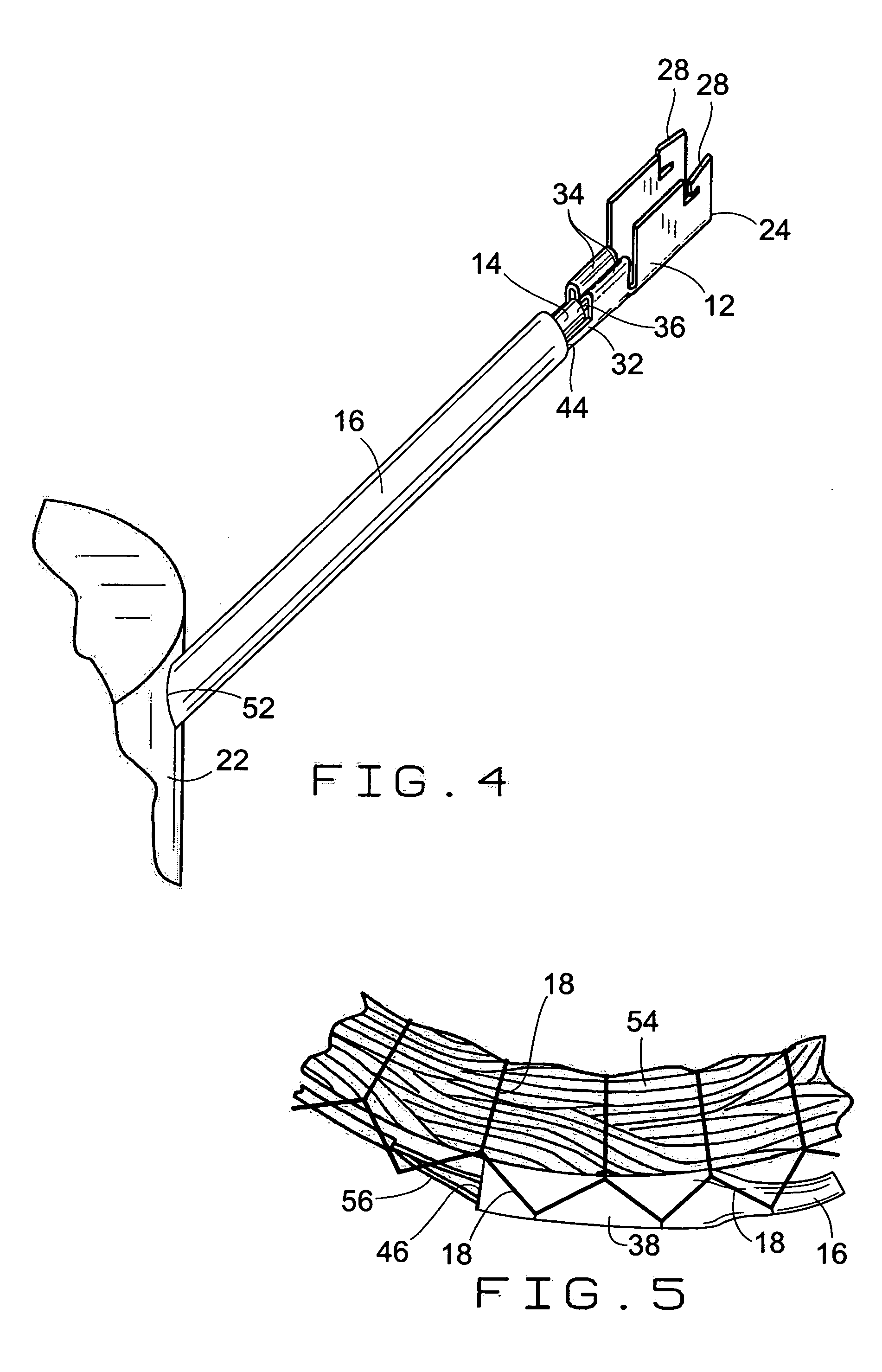
[0014] The electrical connector apparatus of the invention is basically comprised of an electrically conductive terminal (12), a length of electrically conductive wire (14), a tubular insulating sleeve (16), and a mechanical connection (18) employed in connecting the length of wire (14) to an electrical device, such as an electric motor (22).

[0015] The conductive terminal (12) is constructed of an electrically conductive material, for example a metal. As shown in the drawing figures, the terminal (12) has a length with an attaching end (24) at a distal end of its length and a connection end (26) at an opposite, proximal end of its length. The terminal (12) is shown in the drawing figures having a general U-shape cross section. The terminal attaching end (24) is formed with pairs of flanges (28) that are adapted for connecting the terminal (12) to a separate electrical coupling. The configurations of the attaching flanges (28) at the terminal attaching end (24) are illustrative only...


PUM


Abstract

An electrical connector includes a terminal attached to a length of wiring that extends from the stator windings of an electrical device, and a tubular insulating sleeve that extends along the length of wiring. The sleeve is secured stationary relative to both the wiring and the terminal by being secured to the stator windings by the same mechanical connection that binds the stator windings.

Description

BACKGROUND OF THE INVENTION [0001] (1) Field of the Invention [0002] The present invention pertains to an electrical connector that includes a terminal attached to a length of wiring that extends from the stator windings of an electric motor, and a tubular insulating sleeve that extends along the length of wiring. The sleeve is secured stationary relative to both the wiring and the terminal by being secured to the stator windings by the same mechanical connection that binds the stator windings. [0003] (2) Description of the Related Art [0004] Current electrical connector assemblies, such as that disclosed in the U.S. patent of Peters, et al., U.S. Pat. No. 6,410,853, are well-designed for their intended functions. A connector assembly of this type is often employed on the lead wires of an electric motor. The assembly includes a terminal that is secured to the motor lead wire. The terminal is removably attachable to a separate electrical coupling to communicate the motor stator windi...

Claims


Application Information

Patent Timeline
Patent Type & Authority Applications(United States)
IPC IPC(8): H01R9/05
CPCH01R43/048H01R4/185
Inventor FARGO, VINCENT P.WHITE, KENT L.MICHAELS, PAUL G.OLEJNICZAK, JACOB M.RIGGS, WILLIAM L.
Owner HERMETIC MOTORS LP
Learn More