Electrical connector

a technology of electrical connectors and connectors, applied in the direction of electrical discharge lamps, coupling device connections, coupling protective earth/shielding arrangements, etc., can solve the problems of putting more severe pressure on connector manufacturers, and achieve the effect of reducing crosstalk regardless of the length of the connected cabl

Inactive Publication Date: 2006-01-05
DDK LTD
View PDF9 Cites 7 Cited by
  • Summary
  • Abstract
  • Description
  • Claims
  • Application Information

AI Technical Summary

Benefits of technology

[0009] It is an object of the invention to provide an improved electrical connector which, in view of the problems of the prior art described above, achieve

Problems solved by technology

In recent years, with the miniaturization of electric or electronic appliances, the requirement of m

Method used


Image

  • Electrical connector
  • Electrical connector
  • Electrical connector

Examples


Embodiment Construction

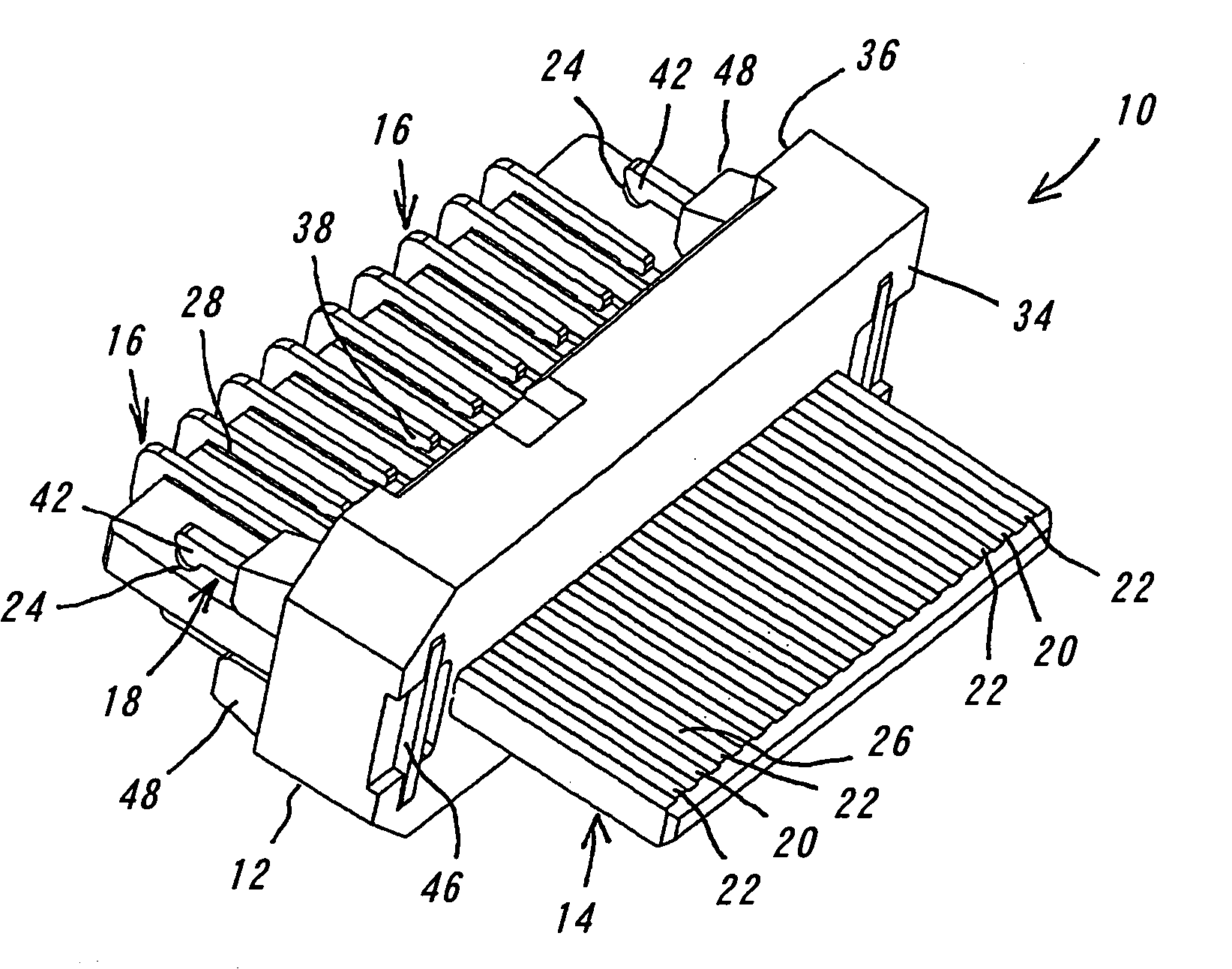
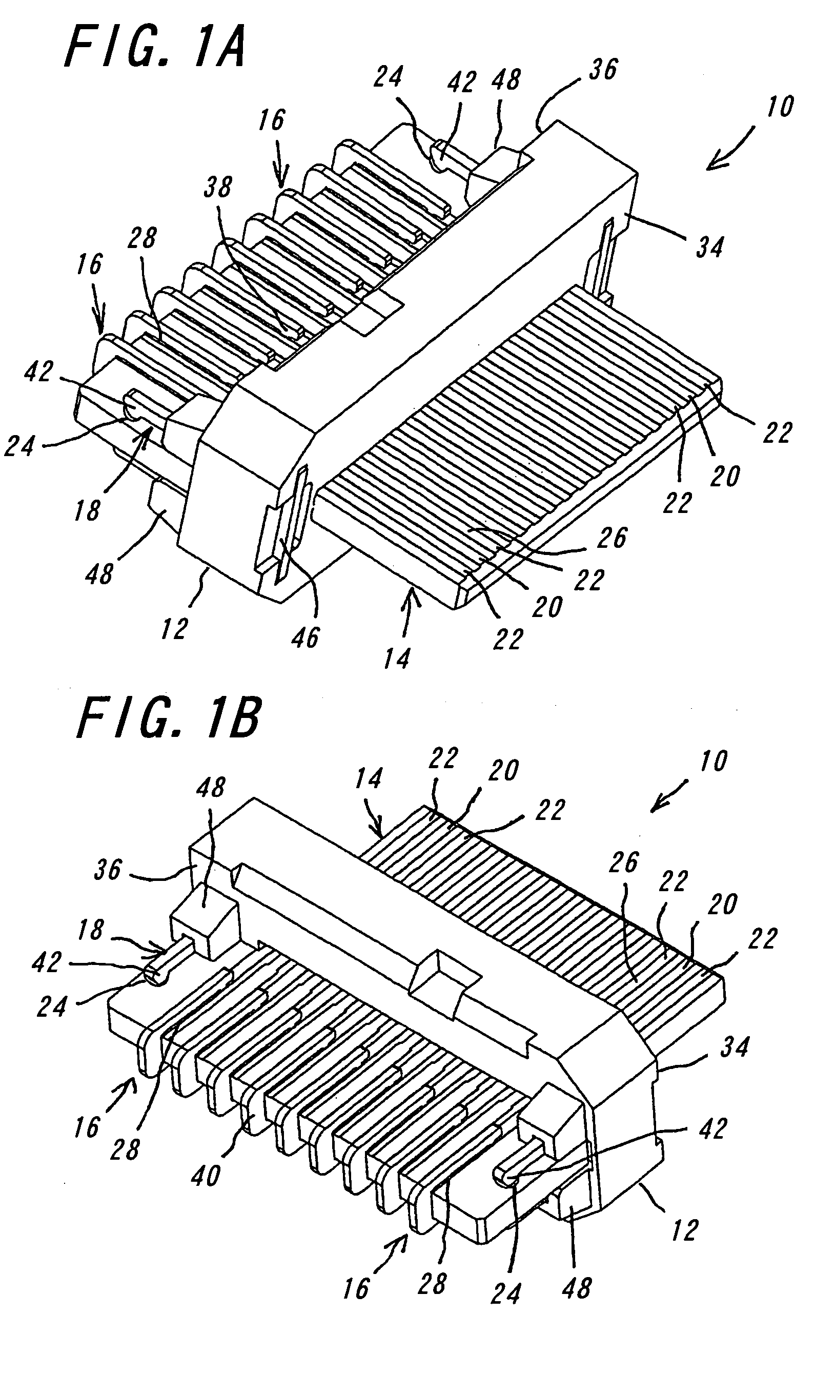
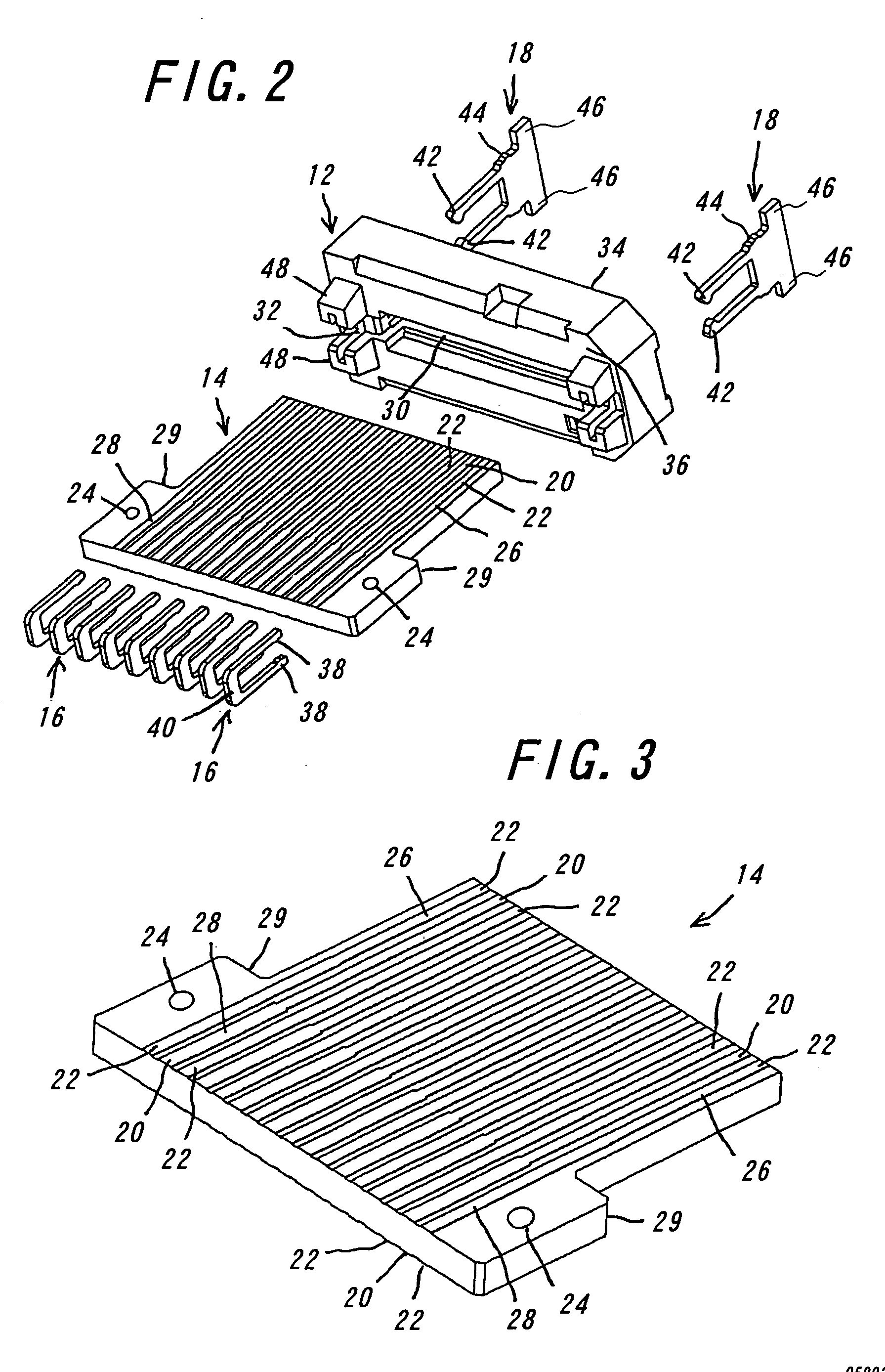
[0027] One embodiment of the electrical connector 10 according to the invention will be explained with reference to FIGS. 1 to 5 hereinafter. FIG. 1A is a perspective view of the electrical connector of the invention viewed from its fitting side, and FIG. 1B is a perspective view of the connector viewed from the connecting side. FIG. 2 is an exploded perspective view of the connector viewed from the connecting side. FIGS. 3, 4 and 5 are perspective views of the substrate, shielding plate and locking member used in the electrical connector according to the invention, respectively.

[0028] The electrical connector 10 of the one embodiment according to the invention mainly comprises a housing 12, a substrate 14, shielding plates 16 and locking members 18. In the electrical connector 10, instead of electric contacts, the substrate 14 is used as a contacting members in contact with mating objects in order to achieve a narrower pitch and hence a miniaturization of the connector 10.

[0029] ...


PUM


Abstract

An electrical connector includes a housing, a substrate, and shielding plates. The housing has an inserting hole for the substrate, and the substrate has a plurality of signal patterns and a plurality of ground patterns alternately arranged on at least one surface of the substrate in a manner that one signal pattern is between two ground patterns. The signal patterns and the ground patterns each have a contact portion to contact a mating object and a connection portion to be connected to a cable. The shielding plates are each connected to the connection portion of the ground pattern for shielding. With this construction, the electrical connector achieves its miniaturization and reduction in crosstalk regardless of length of connected cables.

Description

BACKGROUND OF THE INVENTION [0001] This invention relates to an electrical connector for use in electric or electronic appliances such as servers, super computers and the like, and more particularly to an improved electrical connector capable of minimizing crosstalk when being connected to cables. [0002] In recent years, with the miniaturization of electric or electronic appliances, the requirement of miniaturization for electrical connector has put more severe pressure on manufacturers of connectors. In many cases, generally, an electrical connector comprises insulators formed of electrically insulating materials and electric contacts formed of a conductive material. The electric contacts each comprise a contact portion to contact a mating object, a fixed portion to be fixed to the insulator and a connection portion to be connected to a substrate or a cable. The electric contacts are fixed to the insulator by press-fitting, hooking (lancing) or the like. [0003] As pitches of electr...

Claims


Application Information

Patent Timeline
IPC IPC(8): H01R13/648
CPCH01R13/65807H01R13/6658H01R13/6585H01R13/6471H01R13/6474H01R2201/06
Inventor ISHIZUKA, SHINYAOZAI, KAZUYUKI
Owner DDK LTD
Why Eureka
Try Eureka