
Chain tensioner for two-wheeled vehicle engine

a two-wheeled vehicle engine and chain tensioner technology, which is applied in the direction of belts/chains/gearrings, mechanical equipment, belts/chains/gearrings, etc., can solve the problems of inability to maintain the tension in the chain, the tensioner cannot maintain the tension, and the chain tensioner cannot be sufficiently suppressed

Active Publication Date: 2006-01-05
NTN CORP
View PDF15 Cites 58 Cited by
  • Summary
  • Abstract
  • Description
  • Claims
  • Application Information

AI Technical Summary

Benefits of technology

[0010] According to the present invention, there is provided a chain tensioner comprising a housing having an open front end and a radially inner surface defining a cylinder chamber, a plunger having a radially outer surface and slidably mounted in the cylinder chamber, thereby defining a pressure chamber in the cylinder chamber, the radially inner surface and the radially outer surface defining a clearance therebetween through which hydraulic oil in the pressure chamber can leak, a spring biasing the plunger outwardly of the cylinder chamber, the housing being formed with a hydraulic oil supply passage communicating with the pressure chamber, a check valve for preventing backflow...

Problems solved by technology

As a result, conventional chain tensioners cannot sufficiently suppress high-frequency vibrations of the chain used in such an engine, and / or cannot maintain the tension in the chain to an optimum level in a wide revolving speed range of the engine.
But even such improved chain tensioners cannot still maintain the tension in the chain used in a two-wheeled vehicle engine to an optimum level in a wide temperature range and a wide engine revolution range because the revolution range of a two-wheeled vehicle engine is wide.
For example, if the clamping force is determined at a low level while the engine is rotating at a high speed in order to reduce the tension in the chain, the damping force may be insufficient while the hydraulic oil temperature is high due to low viscosity of the oil.
Conversely, if the damping force is set at a high level, the damping force may be too large when the oil temperature is low and thus high in viscosity.
But only the relief valve cannot sufficiently control the tension in the chain used for a two-wheeled vehicle engine.
But if the vibration frequency is high after the relief valve has opened, the pressure in the pressure chamber may increase in spite of the fact that hydraulic oil is being discharged through the relief valve.
But such a solution may cause a sharp drop in the internal pressure immediately after the relief valve has opened especially if the oil temperature is high and thus its viscosity is low.
This will cause flapping of the chain.
It is difficult to stably keep such frictional resistance.
This solution is however expensive, and still such a film cannot stabilize the operation of the chain tensioner for a sufficiently long period of time if such a tensioner is used for a camshaft driving chain of a two-wheeled vehicle engine.

Method used


Image

  • Chain tensioner for two-wheeled vehicle engine
  • Chain tensioner for two-wheeled vehicle engine
  • Chain tensioner for two-wheeled vehicle engine

Examples


Embodiment Construction

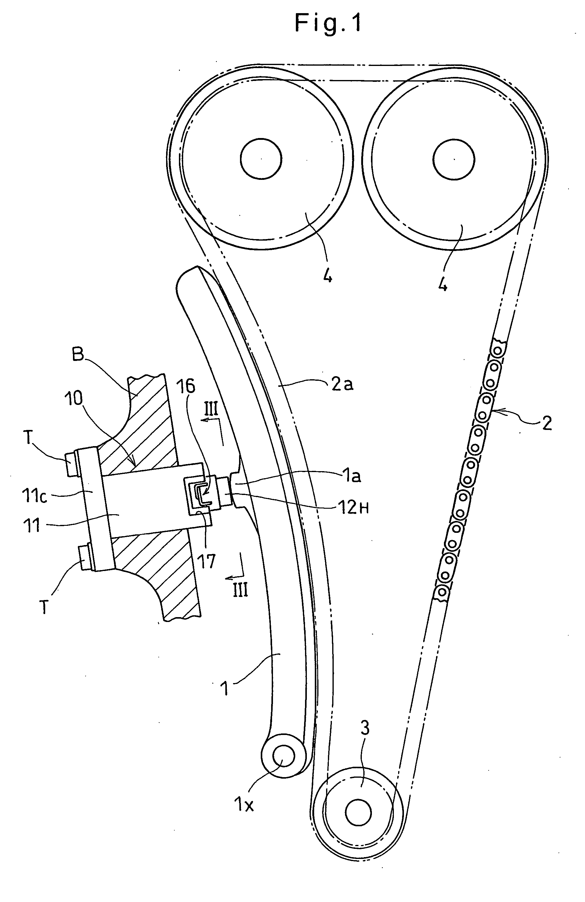
[0025] Now, the embodiment of the invention is described with reference to the accompanying drawings. FIG. 1 is a schematic view of an entire chain system including the chain tensioner embodying the present invention. As shown, the chain tensioner 10 includes a plunger 12 slidably mounted in a housing 11 and having a head 12H pressed against an abutting member 1a of a chain guide 1 pivotable about a shaft lx. The plunger 12 thus presses the chain guide 1 against the slack side 2a of a camshaft driving chain 2, thereby applying tension to the chain 2. The chain 2 connects a pulley 3 on the engine output shaft to pulleys 4 on camshafts. Reference numeral 16 designates a retraction regulating mechanism including a register ring for regulating retraction of the plunger. Numeral 17 designates a cutout.

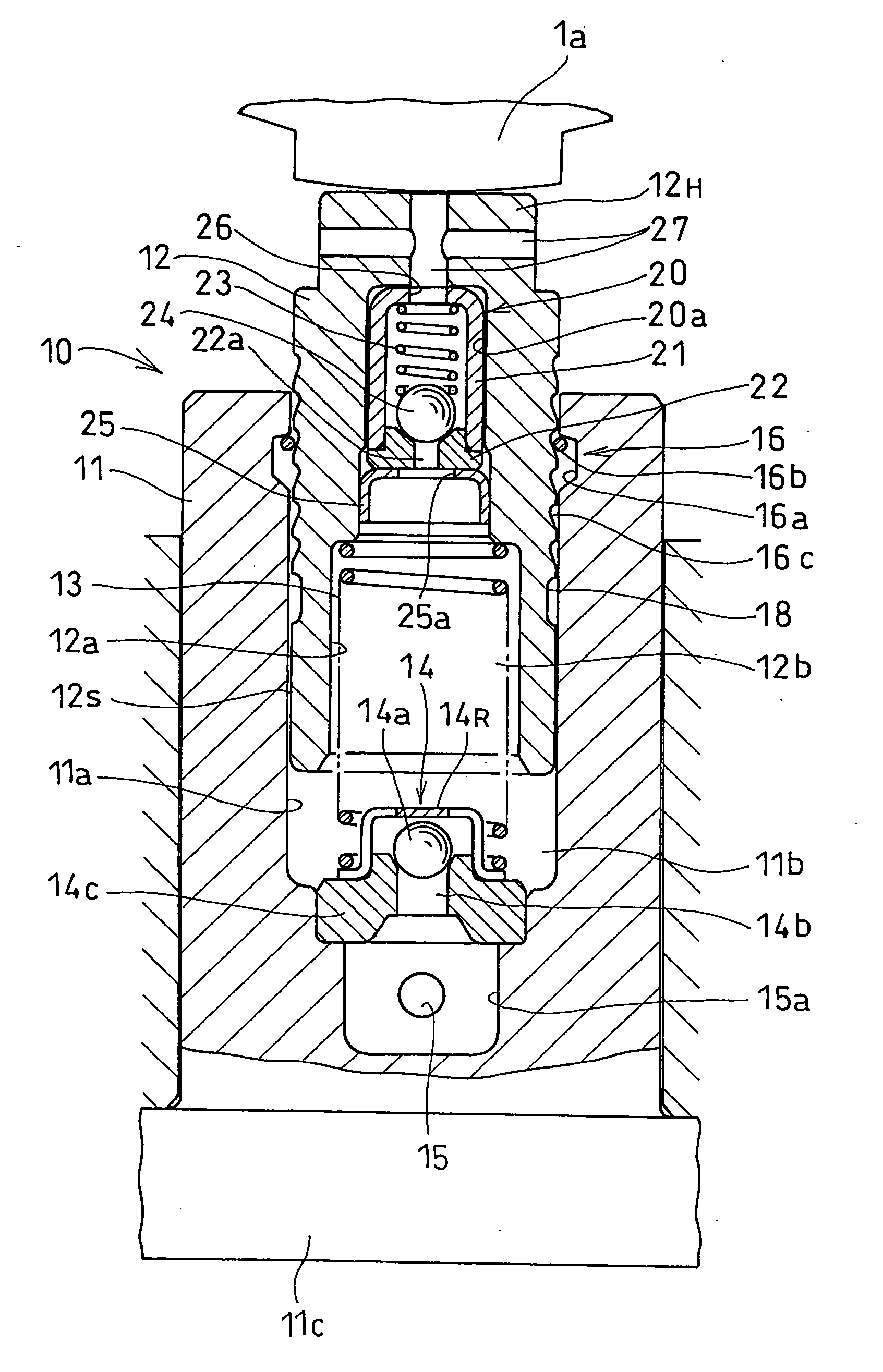
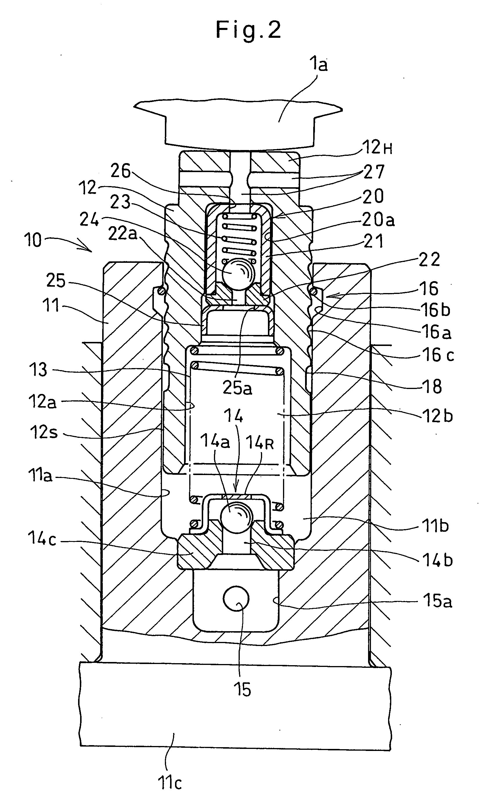
[0026] As shown in FIG. 2, the chain tensioner 10 includes the housing 11, which is formed with a cylinder chamber 11a having an open end, the plunger 12, which is slidably received in the...


PUM


Abstract

A chain tensioner for use in a chain system for driving a vehicle engine, particularly a two-wheeled vehicle engine, includes a housing and a plunger slidably mounted in the cylinder chamber formed in the housing. The plunger is biased outwardly by a return spring mounted in a pressure chamber defined in the cylinder chamber by the plunger. A check valve is provided at the closed end of the cylinder chamber to prevent backflow of hydraulic oil in the pressure chamber. A relief valve is provided in the plunger. The relief valve has a relief pressure above which the relief valve opens, thereby discharging hydraulic oil in the pressure chamber. An oil leakage clearance is defined between the inner wall of the cylinder chamber and the radially outer surface of the plunger through which hydraulic oil in the pressure chamber can leak out. The relief pressure and the radial dimension of the oil leakage clearance are determined such that the tension in the chain is kept at such a level that vibrations of the chain are minimum at any temperature of hydraulic oil and at any revolving speed of the engine.

Description

BACKGROUND OF THE INVENTION [0001] The present invention relates to a chain tensioner for use in a chain system for driving camshafts of a vehicle engine, particularly a vehicle engine that rotates at a high speed such as a two-wheeled vehicle engine. [0002] A chain tensioner is used in a chain system for driving camshafts of a vehicle engine, and typically comprises a housing formed with a cylinder chamber, a plunger slidably mounted in the cylinder chamber of the housing, thereby defining a pressure chamber in the cylinder chamber, and a spring mounted in the pressure chamber to bias the plunger outwardly of the cylinder chamber. The housing is formed with a hydraulic oil supply passage communicating with the pressure chamber. The plunger has its protruding end pressed against a camshaft-driving chain. Hydraulic oil in the pressure chamber clampens the pushing force applied from the chain to the plunger, thereby keeping the tension in the chain at a constant level. As the hydrauli...

Claims


Application Information

Patent Timeline
IPC IPC(8): F16H7/08F16H7/22
CPCF16H7/0836F16H2007/0806F16H2007/0859F16H2007/0853F16H2007/0855F16H2007/0814
Inventor SATO, SEIJIKITANO, SATOSHIHAYAKAWA, HISASHI
Owner NTN CORP
Features
  • Generate Ideas
  • Intellectual Property
  • Life Sciences
  • Materials
  • Tech Scout
  • Unparalleled Data Quality
  • Higher Quality Content
  • 60% Fewer Hallucinations
Learn More