
Offset track

a technology of offset track and rubber track, which is applied in the direction of transportation and packaging, mechanical equipment, packaging, etc., can solve the problems of affecting the operation of equipment, so as to achieve the effect of improving ride, reducing vibration, and high performan

Inactive Publication Date: 2010-01-05
MCLAREN GRP HLDG PTE LTD
View PDF11 Cites 3 Cited by
  • Summary
  • Abstract
  • Description
  • Claims
  • Application Information

AI Technical Summary

Benefits of technology

[0006]An offset track forms a pattern perpendicular to the centerline of the track which enables tracks to be formed with even or odd number of metal inserts and thus accommodate virtually any tracked vehicle. The offset track uses variations in body thickness and lug width to provide a high performance offset track with improved ride, minimum vibration and longer wear. Use of full size and mini-inserts in a single track minimizes the weight and further enhances the performance of an offset track.
[0007]A sprocket driven rubber track may include metal inserts for engaging the drive mechanism of the tracked vehicle. The metal inserts according to the present disclosure include a rounded lip at the outboard edge. The lip operates during the layup of the track to contain the metal cables and during the rubber molding process, the lips prevent the cables from moving outboard under pressure of the rubber flow. The lip is rounded to minimize the likelihood of the lip causing a stress crack emanating from a corner of the lip.
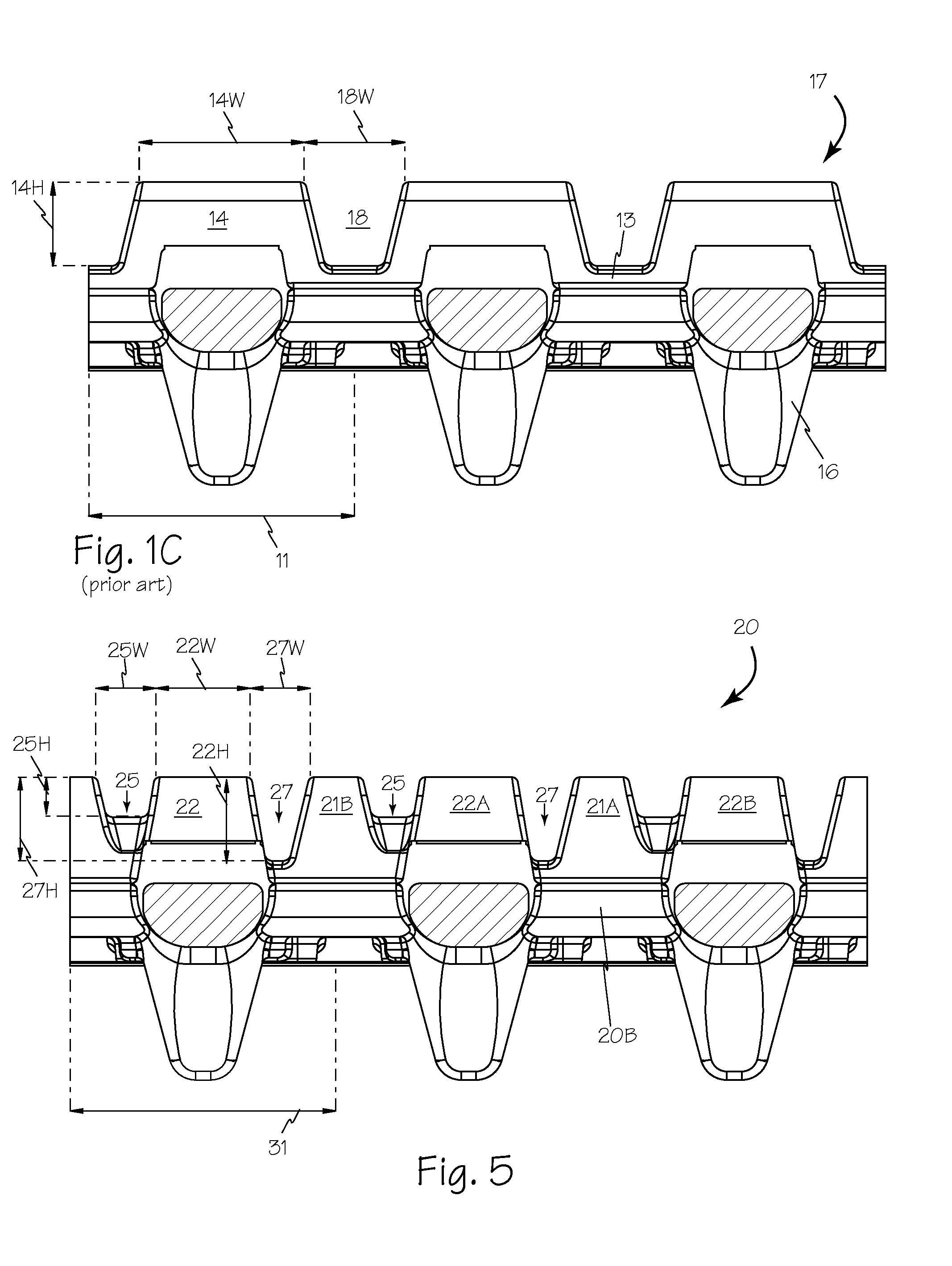
[0008]A sprocket driven rubber track is formed with narrow tread lugs to minimize the propagation of cracks in the rubber of the lugs. On conventional tracks with wide lugs, a crack that propagates across the lug may cause a large chunk of the lug to break off which at a minimum will cause additional vibration as the broken lug engages the ground. Using narrower lugs limits propagation of cracks and results in smaller chunks of lug breaking off thus resulting in a smoother ride and less vibration induced maintenance for the machine.
[0009]A sprocket driven rubber track may also include sprocket hole cuts oriented parallel and perpendicular to the centerline of the track to minimize the open space and prevent debris from fouling the drive mechanism when the sprocket engages the hole.
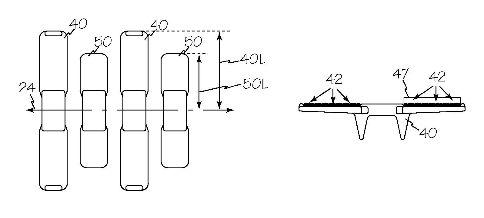
[0010]In an alternate configuration, a rubber track may include metal inserts of different sizes to reduce cost and weight and improve flexibility of the track. Mini-inserts may alternate with full size inserts to provide modest weight savings and the ratio of full size metal inserts to mini-inserts may vary according to the weight of the vehicle, the track strength requirements and the required track flexibility. The length of the mini-inserts may also vary from the full size metal insert to the smallest practical insert which engages no less than 20% of the width of each wire belt within the track. Each track may have a variety of different length metal inserts in a single track to permit customizing the weight and flexibility of a track to a particular machine and the expected work environment.
[0011]Metal inserts to be installed in a rubber track may also include one or more ribs, ridges, troughs or holes to provide additional surface area for adhesion to the rubber of the track. The additional surface area is particularly important for inserts that are smaller than a full size insert and prevents the smaller inserts from breaking loose from the track when under load.

Problems solved by technology

Conventional rubber tracks for construction equipment are an expensive component and may be responsible for many problems that plague the equipment.
Most tracked equipment does not have suspension and thus any vibrations or shocks created, fostered or enhanced by the tracks travel directly to the equipment and contribute to operator fatigue and equipment wear and failure.
However larger lugs also enable the inevitable cracks that form in the rubber to grow in a larger lug and thus when a chunk of rubber breaks off, it is a large chunk and will exacerbate the uneven ride and vibrations inherent in conventional offset tracks.
This leads to most tracks falling apart long before they wear out.
On conventional tracks with wide lugs, a crack that propagates across the lug may cause a large chunk of the lug to break off which at a minimum will cause additional vibration as the broken lug engages the ground.

Method used


Image

  • Offset track
  • Offset track
  • Offset track

Examples


Embodiment Construction

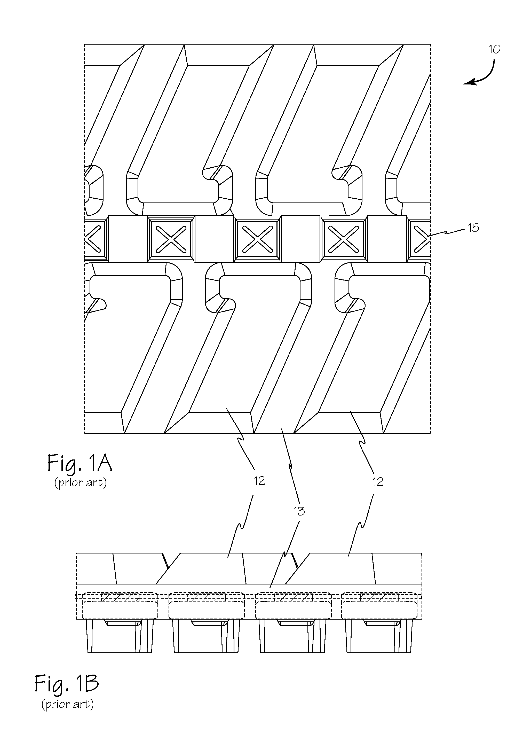
[0039]In conventional tracks such as the conventional offset track 10 of FIG. 1A and FIG. 1B, lugs such as lugs 12 are separated by track body 13. Sprocket holes such as sprocket hole 15 are often provided with cutouts rotated 45° from the track centerline, in the form of an X shape, to enable the drive sprockets to extend through track body 13.

[0040]In a continuous track with variable lug width such as track 20 ofFIG. 2, FIG. 3 and FIG. 4, the width of lugs such as joint lug 21 and insert lug 22 may alternate to provide an offset pattern with the lugs perpendicular to centerline 24. The dimensions of recesses such as reinforced recess 25 and recess 27 alternate according to offset pattern 28. Reinforced recesses 25 alternate with open recesses 27 along the track, parallel with the track centerline, and the recesses also alternate across the track centerline. The alternation of unreinforced recesses or open recesses 27 promotes track flex and the alternation of the reinforced recess...


PUM


Abstract

An offset track forms a pattern perpendicular to the centerline of the track which enables tracks to be formed with even or odd number of metal inserts and thus accommodate virtually any tracked vehicle. The offset track uses variations in body thickness and lug width to provide a high performance offset track with improved ride, minimum vibration and longer wear. Use of full size and mini-inserts in a single track minimizes the weight and further enhances the performance of an offset track.

Description

RELATED APPLICATIONS[0001]This application claims priority from copending U.S. Provisional patent application No. 60 / 904,226 filed Feb. 28, 2007.FIELD OF THE INVENTIONS[0002]The inventions described below relate to the field of tracked construction equipment and more specifically to rubber tracks with metal inserts for construction equipment.BACKGROUND OF THE INVENTIONS[0003]Conventional rubber tracks for construction equipment are an expensive component and may be responsible for many problems that plague the equipment. Most tracked equipment does not have suspension and thus any vibrations or shocks created, fostered or enhanced by the tracks travel directly to the equipment and contribute to operator fatigue and equipment wear and failure.[0004]Conventional thinking about offset tracks teaches that bigger lugs provided longer wear. However larger lugs also enable the inevitable cracks that form in the rubber to grow in a larger lug and thus when a chunk of rubber breaks off, it i...

Claims


Application Information

Patent Timeline
Patent Type & Authority Patents(United States)
IPC IPC(8): B62D55/24
CPCB62D55/244B62D55/205B62D55/20
Inventor DOYLE, RICHARDSON J.
Owner MCLAREN GRP HLDG PTE LTD
Learn More