Eureka AIR delivers breakthrough ideas for toughest innovation challenges, trusted by R&D personnel around the world.

Forward looking optical coherence tomography endoscope

an endoscope and optical coherence technology, applied in the field of endoscopy, can solve the problems of not being satisfactory, unable to readily determine the depth of tumor invasion by either method, and the relative survival rate of 5 years is less than 20%, and achieves the effects of low external vibration of the probe, low cost, and high resolution

Inactive Publication Date: 2012-12-04
BOARD OF SUPERVISORS OF LOUISIANA STATE UNIV & AGRI & MECHANICAL COLLEGE
View PDF10 Cites 3 Cited by
  • Summary
  • Abstract
  • Description
  • Claims
  • Application Information

AI Technical Summary

Benefits of technology

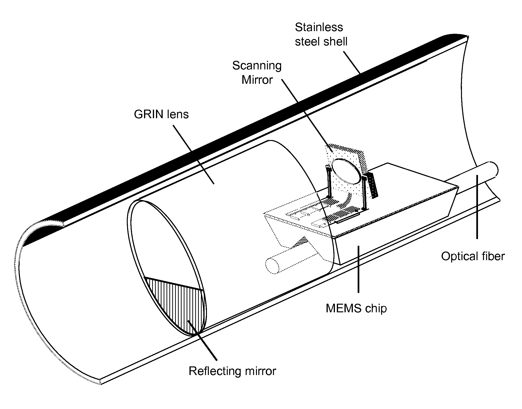
[0021]We have discovered a forward-looking, optical coherence tomography, endoscopic probe capable of high resolution with a small diameter, for example, 2 mm, 1.75 mm, 1.5 mm, 1.25 mm, 1 mm or smaller. Images may be two-dimensional (slices) or three-dimensional (volume). As illustrated schematically in FIG. 3, light is focused and scanned during three passes through a lens. A light source, preferably an optical fiber, supplies light near one edge of the proximal side of the lens, preferably a GRIN lens. The light makes a first pass through the lens from the proximal side to the distal side, and is reflected from a fixed mirror (e.g., silvered surface) on the distal side of the lens. The reflected light then makes a second pass through the lens from the distal side to the proximal side, and exits the lens at the proximal side, preferably as a parallel beam, and is then reflected by an external scanning mirror, preferably a MEMS device. The scanned, reflected light then makes a third pass through the lens from the proximal side to the distal side, and passes to a sample to be imaged. The light is focused onto an image plane, which may for example be on the surface of or in the interior of the sample. Light reflected from the sample passes back through the same system, and is focused on and collected by the optical fiber. The light collected by the fiber is used to construct a high-quality image, using techniques otherwise known in the art to deconvolve and construct two-dimensional or three-dimensional images, for example by analyzing interference with a reference beam in a Michelson-type interferometer. External vibration of the probe is minimal. The probe can be adapted for flexible or rigid applications.

Problems solved by technology

Unfortunately, few gastric cancers are discovered at an early stage in the United States, leading to 5-year relative survival rates of less than 20%.
Although diagnostic advances in endoscopy techniques and double-contrast barium studies allow the detection of small lesions early in the course of the disease, the depth of tumor invasion cannot readily be determined by either of these methods.
Nevertheless, results are still not satisfactory, especially for evaluating tumor depth.
However, even with dynamic CT scanning, it is well known that gastric cancers located on the horizontally-oriented portion of the gastric wall are difficult to detect due to poor z-axis resolution and the partial volume averaging effect.
Although recent improvements in CT techniques have overcome some of the limitations of conventional axial CT, and while they allow improved tumor detection and localization, the detection of early gastric cancers in the absence of a thickened gastric wall remains difficult.
To our knowledge, no prior OCT imaging has successfully visualized gastric submucosa.
In prior forward-looking endoscopes the mechanisms used to scan have either required relatively wide probes, or the design of the probes makes them prone to vibration, neither of which is desirable.
It would be desirable to reduce the diameter to 1.5 mm, 1.25 mm, 1 mm or even smaller, but such a small diameter is difficult to achieve with existing designs.
Yet, a scanning mechanism tends to increase the diameter of the probe, which is undesirable, or it results in a sideways-looking probe rather than a forward-looking probe.
Other types of forward-looking probes that have been reported include one in which a distal scanning mirror is placed alongside a GRIN lens, which approximately doubles the diameter of the probe; and one in which a complex counter-rotation system with two GRIN lenses is employed, which is mechanically complex, rigid, and may be prone to vibration.
Because lenses with relatively high masses rotate rapidly through 360 degrees, as opposed to scanning through relatively smaller angles with a relatively low-mass mirror, this probe may be prone to undesirable vibrations and may, perhaps, be less reliable mechanically as compared to designs based on lower-mass scanning mirrors.
The design of the probe makes it inherently prone to vibration, and may make it difficult to implement three-dimensional scanning.
This type of endoscope is rigid, limiting usefulness for gastric (and other types of) imaging.

Method used


Image

  • Forward looking optical coherence tomography endoscope
  • Forward looking optical coherence tomography endoscope
  • Forward looking optical coherence tomography endoscope

Examples


example 1

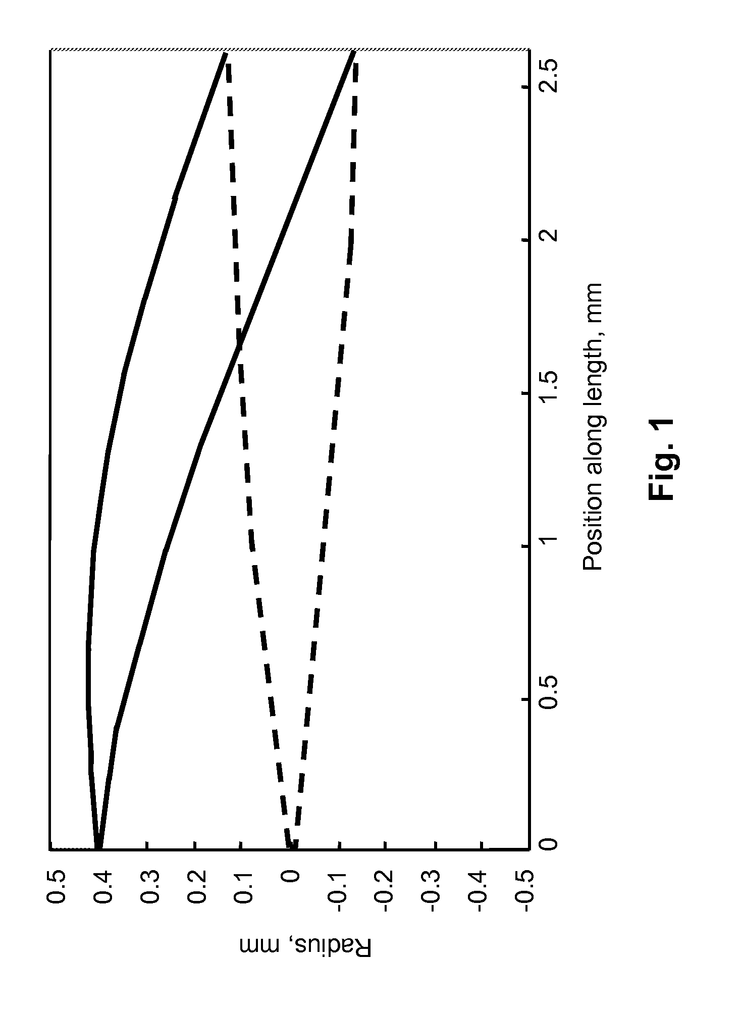
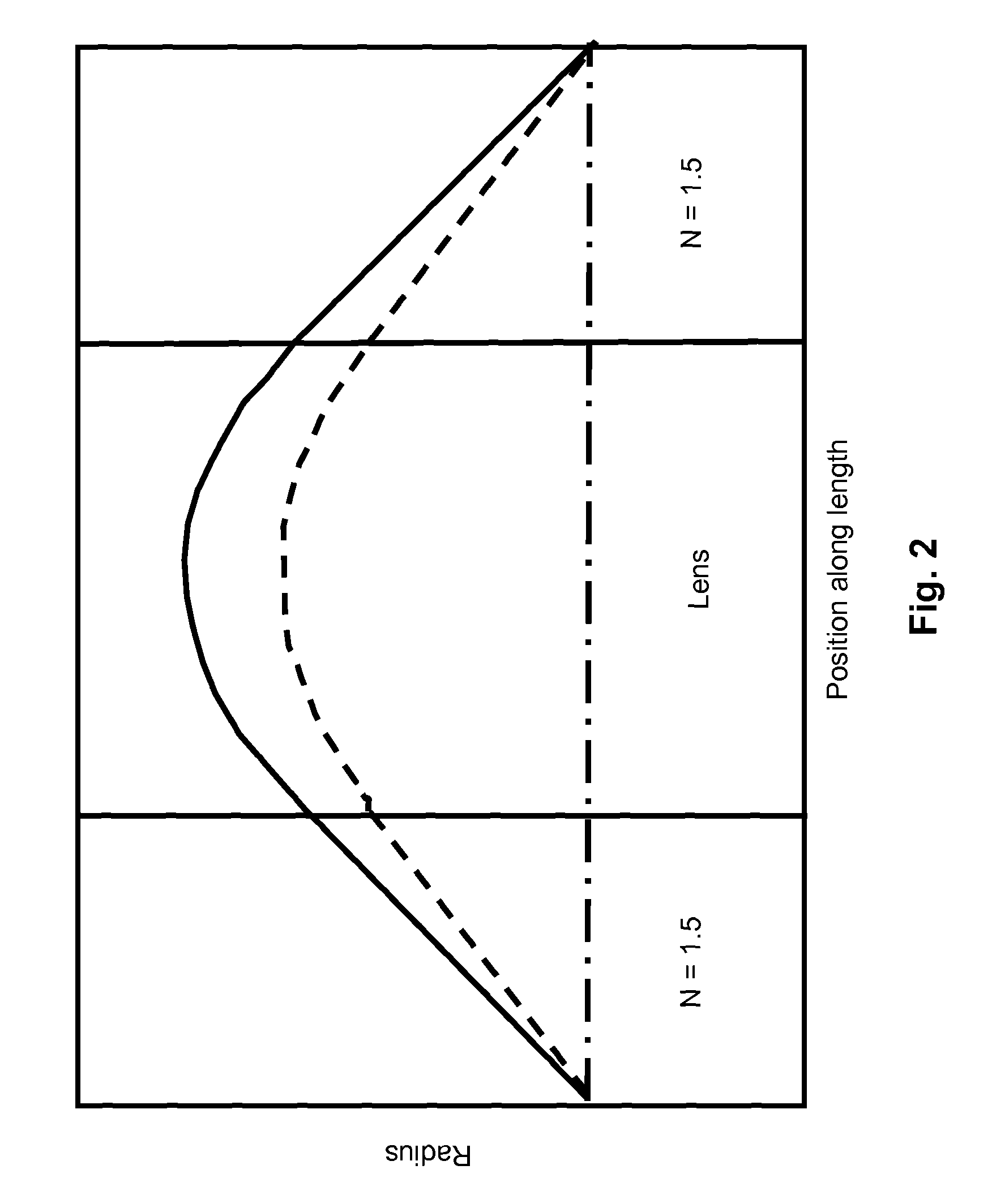
[0039]A simulation of the optical system was first conducted with large scale components. The distributed focusing of a π / 4 GRIN lens was approximated with a series of three equally-spaced conventional lenses. A HeNe laser beam at a wavelength of 0.633 μm was focused by a microscope objective to a numerical aperture of 0.12 at the entrance to the lens, approximately the same numerical aperture as that for light entering the GRIN lens in the system depicted in FIG. 3. The laser light then made three passes through the lenses and was reflected from the mirrors as shown, before coming to a sharp focus downstream from the lens. This experiment demonstrated in principle the successful use of the novel optical system.

example 2

[0040]FIG. 4 depicts a side-viewing endoscope OCT system for comparison. In many respects, except for those features of the new system that are novel, the new system may be operated in a generally similar manner to that used for a side-viewing endoscope OCT system. There is a superluminescent light source having a center wavelength of 1300 nm and a 100 nm bandwidth (Superlum D1300-HP, Moscow, Russia), for a coherence length on the order of 10 μm. A center wavelength of 1300 nm was chosen because of the ready availability of photonics components, and because tissue attenuation at that wavelength is low, allowing relatively deep imaging. Light from the source is split by a fiber-based Michelson interferometer into two paths: one path travels to the sample arm, where light is focused onto tissue or other sample; and one path travels to a reference arm, which includes a Fourier-domain, rapid-scanning optical delay line to modulate the optical path length. A relatively low coherence leng...

example 3

[0042]To demonstrate the feasibility in principle of imaging the interior of a rat stomach through OCT, a side-firing OCT system was used to image excised specimens. The stomachs of three rats were excised, opened, rinsed with saline, and pinned flat to a wax block. The light source used was an 890 nm superluminescent diode. The OCT system had a resolution of approximately 8 μm. Images 1 mm deep by 6 mm lateral were successfully taken. The OCT system easily imaged through the thin (250-300 μm) layers of the stomach, and all major layers could be identified. Blood vessels were also visible. This preliminary study demonstrated that OCT can perform imaging that would be useful, for example, in diagnosing gastric cancer. To enhance in vivo image quality, it is preferred to place the animals (or patients) on a liquid diet (e.g., Pedialyte™) for ˜12 hours before imaging, to reduce solids content in the stomach.


PUM


Abstract

A forward-looking, optical coherence tomography, endoscopic probe is disclosed capable of high resolution with a small diameter. Light is focused and scanned during three passes through a lens. A light source supplies light to the proximal side of the lens. The light makes a first pass through the lens, and is reflected from a fixed mirror on the distal side. The reflected light makes a second pass from the distal side to the proximal side, and exits the lens at the proximal side, and is reflected by a scanning mirror. The light makes a third pass through the lens from the proximal side to the distal side to a sample to be imaged. The light is focused during each of the three passes through the lens. Light reflected from the sample passes back through and is focused by the same system.

Description

[0001]This is the United States national stage of international application PCT / US2007 / 080765, international filing date 09 Oct. 2007, which claims the benefit of the 12 Oct. 2006 filing date of U.S. provisional patent application Ser. No. 60 / 851,201 under 35 U.S.C. §119(e).TECHNICAL FIELD[0002]This invention pertains to endoscopy; particularly to a forward-looking, optical coherence tomography endoscope probe having a small outer diameter.BACKGROUND ART[0003]There is a continuing, unfilled need for improved endoscopic techniques, methods and apparatus to obtain optical images of tissue inside a patient, while minimizing the patient's discomfort and minimizing any damage caused by the imaging probe itself. In particular, there is an unfilled need for a forward-looking, optical coherence tomography endoscope probe having a small outer diameter. Existing probes are either side-firing, or if forward-looking have a large diameter or otherwise have an unduly complex construction.[0004]On...

Claims


Application Information

Patent Timeline
Patent Type & Authority Patents(United States)
IPC IPC(8): A61B1/06G02B26/08
CPCA61B5/0062A61B5/0066A61B5/415A61B5/418A61B5/6852G01B9/0205G01B9/02091A61B5/0084G01B2290/35
Inventor FELDMAN, MARTINHAH, DOOYOUNG
Owner BOARD OF SUPERVISORS OF LOUISIANA STATE UNIV & AGRI & MECHANICAL COLLEGE
Why Eureka
Eureka Blog
Learn More