Exercise device

a technology of exercise device and hip joint, which is applied in the field of exercise device, can solve the problems of restricted hip joint movement range, damaged waist, and difficulty in studying the “knee/waist same side type of action” depending on the person, so as to ensure the size of the range of operation, effectively strengthen the muscles, and strengthen the muscular power of the trunk

Inactive Publication Date: 2006-01-05
THE UNIV OF TOKYO
View PDF15 Cites 23 Cited by
  • Summary
  • Abstract
  • Description
  • Claims
  • Application Information

AI Technical Summary

Benefits of technology

[0016] By adopting a configuration where the rotational shaft of the swing arm moves in a horizontal direction forwardly and rearwardly in line with the angle of rotation of the swing arm, the present invention achieves the following results. First, it is possible to ensure the size of the range of operation of the leg and trunk containing the hip joints, pelvis and thoracic vertebrae. In the event that the fulcrum of rotation of the prior art is fixed, the locus of movement of the swing arm traces a circular arc taking the length of the swing arm as a radius. In this respect, with the apparatus of the present invention, the path of travel of the swing arm can be made to be a U-shape by having the fulcrum of rotation of the swing arm move forwardly and rearwardly in synchronization with swinging of the swing arm forwardly and rearwardly. Giving a more detailed description, according to the exercise device of the present invention, with the swinging of the swing arm forwardly and rearwardly, a pad portion restraining the leg of the user travels along a U-shaped path of travel with the position of a vertical posture being the bottom. As a result of the pad portion traveling along a U-shaped pa

Problems solved by technology

However, with exercise devices where the arm rotation fulcrum is a fixed type, there is the drawback that the range of movement of the hip joints is restricted.
When the arm travels along such a circular arcuate path, there is risk involved in that a relatively strong load is placed on the waist that may cause the waist to be damaged as the arms a

Method used


Image

  • Exercise device
  • Exercise device
  • Exercise device

Examples


Embodiment Construction

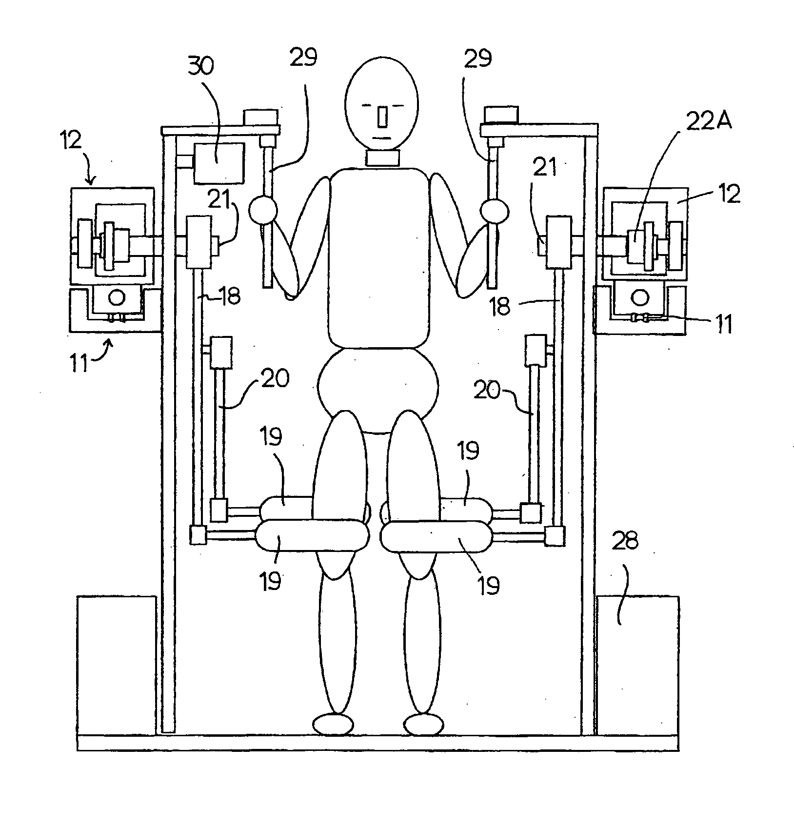
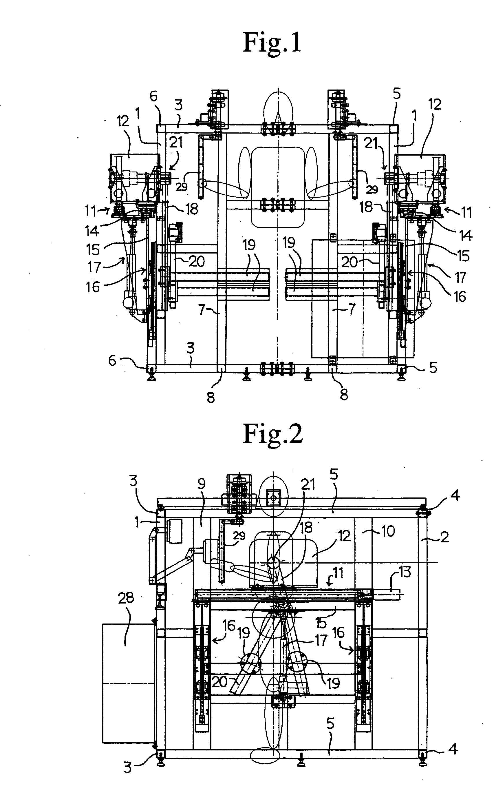
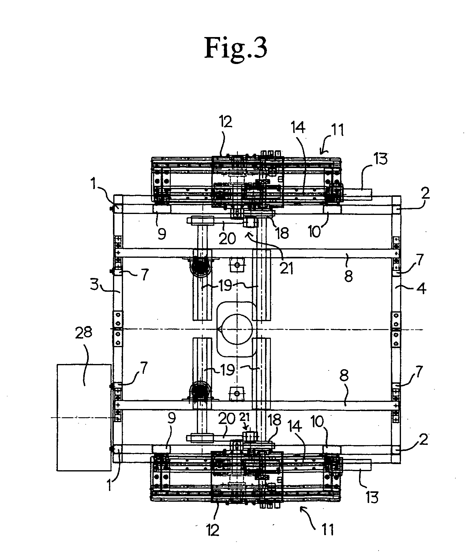
[0031] A description is given of the present invention based on taking a standing operation-type exercise device as an embodiment. FIG. 1 to FIG. 3 are an overall front view, overall side view, and overall plan view of the present invention. An exercise device has a box-shaped frame body comprised of a pair of front vertical frames 1, a pair of rear vertical frames, a plurality of lateral frames 3, 4, 5 and 6 linking the bottom ends and top ends of the vertical frames 1 and 2 from the front to rear, and the left to right, a pair of vertical frames 7 linking between the front lateral frames 3 in a vertical direction, and a pair of lateral frames 8 linking between the front and rear lateral frames forwardly and rearwardly.

[0032] A pair of left and right front posts 9 and a pair of left and right rear posts 10 stand up in parallel with the vertical frames 1 and 2 between forwardly and rearwardly extending the upper and lower lateral frames 5 and 6. Guide members 11 extending horizonta...


PUM


Abstract

The present invention relates to an exercise device to simulate a leg swing motion. The device comprises a frame, a longitudinal guide supported by the frame, and a moveable body reciprocally moveable along the guide. The moveable body has a pivot axis defined thereon. A swing arm is pivotally coupled to the moveable body about the pivot axis such that the moveable body moves rearwardly when the swing arm swings forwardly by a forwardly leg swing motion and the moveable body moves forwardly when the swing arm swings rearwardly by a rearwardly leg swing motion.

Description

BACKGROUND OF THE INVENTION [0001] 1. Field of the Invention [0002] The present invention relates to an exercise device, and particularly relates to an exercise device with the purpose of strengthening leg muscles, hip joints, and muscle groups of the waist. [0003] 2. Description of Related Art [0004]“Hip extension machine hip”, “flexing machines” and etc. are known as exercise devices for working leg muscles and muscle groups of the waist in a standing posture. With these exercise devices, a swing arm rotation fulcrum is fixed. [0005] However, with exercise devices where the arm rotation fulcrum is a fixed type, there is the drawback that the range of movement of the hip joints is restricted. Further, with exercise devices where the rotation fulcrum is fixed, swinging of the arm traces a locus that is part of a circular arc. When the arm travels along such a circular arcuate path, there is risk involved in that a relatively strong load is placed on the waist that may cause the wais...

Claims


Application Information

Patent Timeline
IPC IPC(8): A63B15/02A63B22/00A63B21/00A63B21/005A63B21/06A63B23/02A63B23/04A63B23/12
CPCA63B21/005A63B21/159A63B23/03508A63B23/03541A63B2225/09A63B2023/0452A63B2208/0204A63B2220/833A63B23/0482
Inventor KOBAYASHI, KANDO
Owner THE UNIV OF TOKYO
Why Eureka
Try Eureka