
Tip configurations for a multi-lumen catheter

a multi-lumen catheter and configuration technology, applied in the direction of multi-lumen catheters, catheters, other medical devices, etc., can solve the problems of reducing the possibility of recirculation, and achieve the effect of reducing recirculation and improving fluid throughput efficiency

Active Publication Date: 2006-01-05
CR BARD INC
View PDF99 Cites 161 Cited by
  • Summary
  • Abstract
  • Description
  • Claims
  • Application Information

AI Technical Summary

Benefits of technology

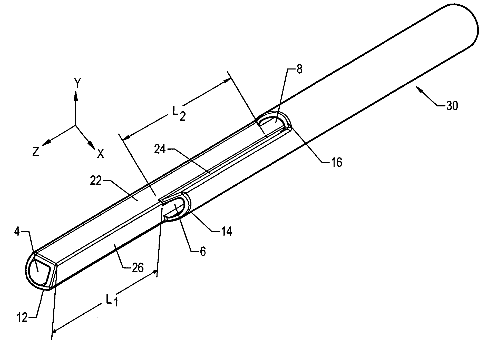
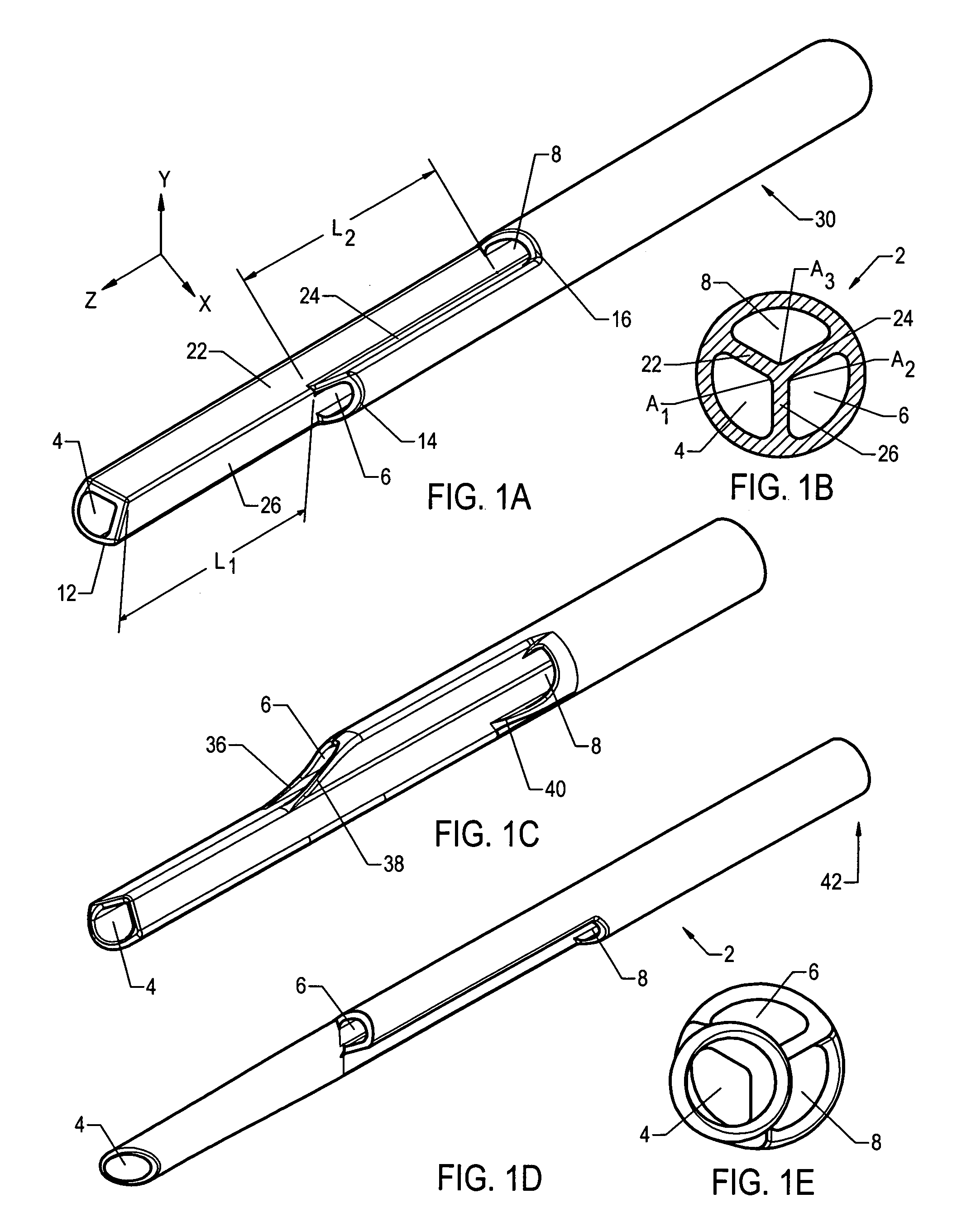
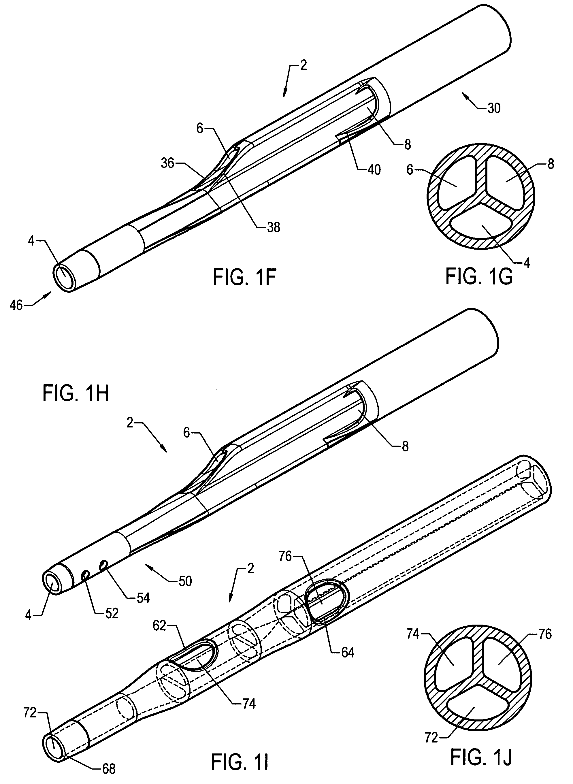
[0010] Accordingly, described herein are various multi-lumen catheters each having three or more lumens where at least two of the lumens have distal openings that are staggered along the length of the catheter. The distal openings of the catheters are arranged in various configurations. These modified catheter configurations may improve fluid throughput efficiency and decrease recirculation in the catheter.
[0012] In another variation, the catheter comprises two or more lumens exiting at the distal end of the catheter, and at least one lumen exiting proximally along the length of the catheter. In one example, the catheter comprises three lumens, with two of the three lumens exiting distally and the third lumen exiting proximally. Preferably, the third lumen is centrally located relative to the two other lumens. The separation between the single proximal and the dual distal lumens may decrease the possibility of recirculation while maximizing flow rate. The catheter may further comprise a beveled tip for increasing the catheter's ease of insertion while keeping infusates injected through the lumens separate until entering the high blood volume regions of the body.

Problems solved by technology

The separation between the single proximal and the dual distal lumens may decrease the possibility of recirculation while maximizing flow rate.

Method used


Image

  • Tip configurations for a multi-lumen catheter
  • Tip configurations for a multi-lumen catheter
  • Tip configurations for a multi-lumen catheter

Examples


Embodiment Construction

[0048] The following detailed description should be read with reference to the drawings, in which like elements in different drawings are identically numbered. The drawings, which are not necessarily to scale, depict selected preferred embodiments and are not intended to limit the scope of the invention. The detailed description illustrates by way of example, not by way of limitation, the principles of the invention. This description will clearly enable one skilled in the art to make and use the invention, and describes several embodiments, adaptations, variations, alternatives and uses of the invention, including what is presently believed to be the best mode of carrying out the invention.

[0049] Before describing the present invention, it is to be understood that unless otherwise indicated this invention need not be limited to applications in humans. As one of ordinary skill in the art would appreciate, variations of the invention may be applied to other mammals as well. Moreover,...


PUM


Abstract

Multi-lumen catheters with improved tip configurations, including a triple-lumen catheter which may be useful for apheresis. In one variation, the catheter has three lumens with distal openings angularly spaced apart and staggered axially with respect to one another. In another variation, the catheter has two lumens exiting distally and one centrally positioned lumen exiting proximally. A third variation is a catheter with a single distal opening and two proximal openings. The staggered lumen openings along the axial length of the catheter may decrease recirculation while maximizing flow rates.

Description

CROSS-REFERENCE TO RELATED APPLICATIONS [0001] Not applicable. STATEMENT REGARDING FEDERALLY SPONSORED RESEARCH OR DEVELOPMENT [0002] Not applicable. REFERENCE TO A COMPACT DISK APPENDIX [0003] Not applicable. BACKGROUND OF THE INVENTION [0004] In various medical applications catheters with three or more lumens are needed to deliver and / or withdraw fluid from the patients' circulatory system. For example, the physician may need to divert blood from the circulatory system through a first lumen in the catheter and at the same time reintroduce the removed blood back into the circulatory system through a second lumen. A third lumen in the catheter may be used to introduce medications and / or nutrition supplements. In another example, each of the lumens within a multi-lumen catheter may be used to introduce a different drug into a patient's circulatory system. The use of separate lumens for each drug may prevent premature mixing of the medications. [0005] One common application of a tripl...

Claims


Application Information

Patent Timeline
IPC IPC(8): A61M37/00A61M3/00
CPCA61M1/3653A61M2202/0413A61M25/0032A61M25/0068A61M25/007A61M2025/0031A61M2025/0036A61M2025/0073A61M1/16A61M25/0026A61M39/02A61M39/105A61M1/3661A61M5/1408A61M2202/0021A61M25/003A61M1/3656A61M1/3659
Inventor HAMATAKE, BRETSTATS, JASON R.OROME, AMIRBARRETT, JOSEPH H.HERZOG, DALLEN GLEN
Owner CR BARD INC
Learn More