Assembled disc spacers

a disc spacer and assembly technology, applied in the field of spinal surgery, can solve the problems of reduced disc degeneration treatment effect, and reduced disc degeneration treatment effect, and achieve the effect of reducing the pressure on the vertebral endpla

Inactive Publication Date: 2006-01-05
FERREE BRET A +1
View PDF20 Cites 44 Cited by
  • Summary
  • Abstract
  • Description
  • Claims
  • Application Information

AI Technical Summary

Benefits of technology

[0006] The present invention improves upon disc spacers (DS) in several ways. Importantly, the invention may be used to assemble DS within a disc space, allowing them to be inserted through smaller openings in the Annulus Fibrosus (AF). The large size of the assembled DS decreases the pressure on the vertebral endplates.

Problems solved by technology

The nucleus becomes thinner and less able to handle compression loads.
The redundant annular fibers are less effective in controlling vertebral motion.
Current surgical treatments of disc degeneration are destructive.
These destructive procedures lead to acceleration of disc degeneration.
The first two groups of procedures compromise the treated disc.
The additional stress results in premature disc degeneration of the adjacent discs.
The large size of TDRs and the rigidity of TDRs make insertion from a posterior approach to the spine dangerous.

Method used


Image

  • Assembled disc spacers
  • Assembled disc spacers
  • Assembled disc spacers

Examples


Embodiment Construction

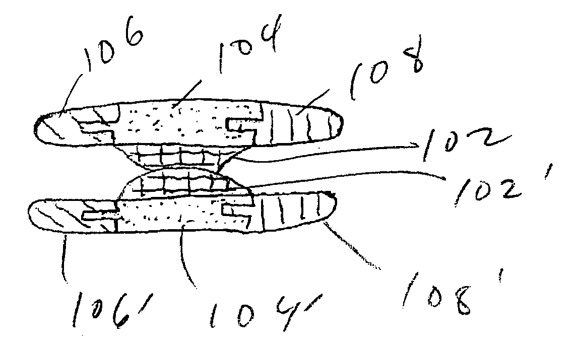
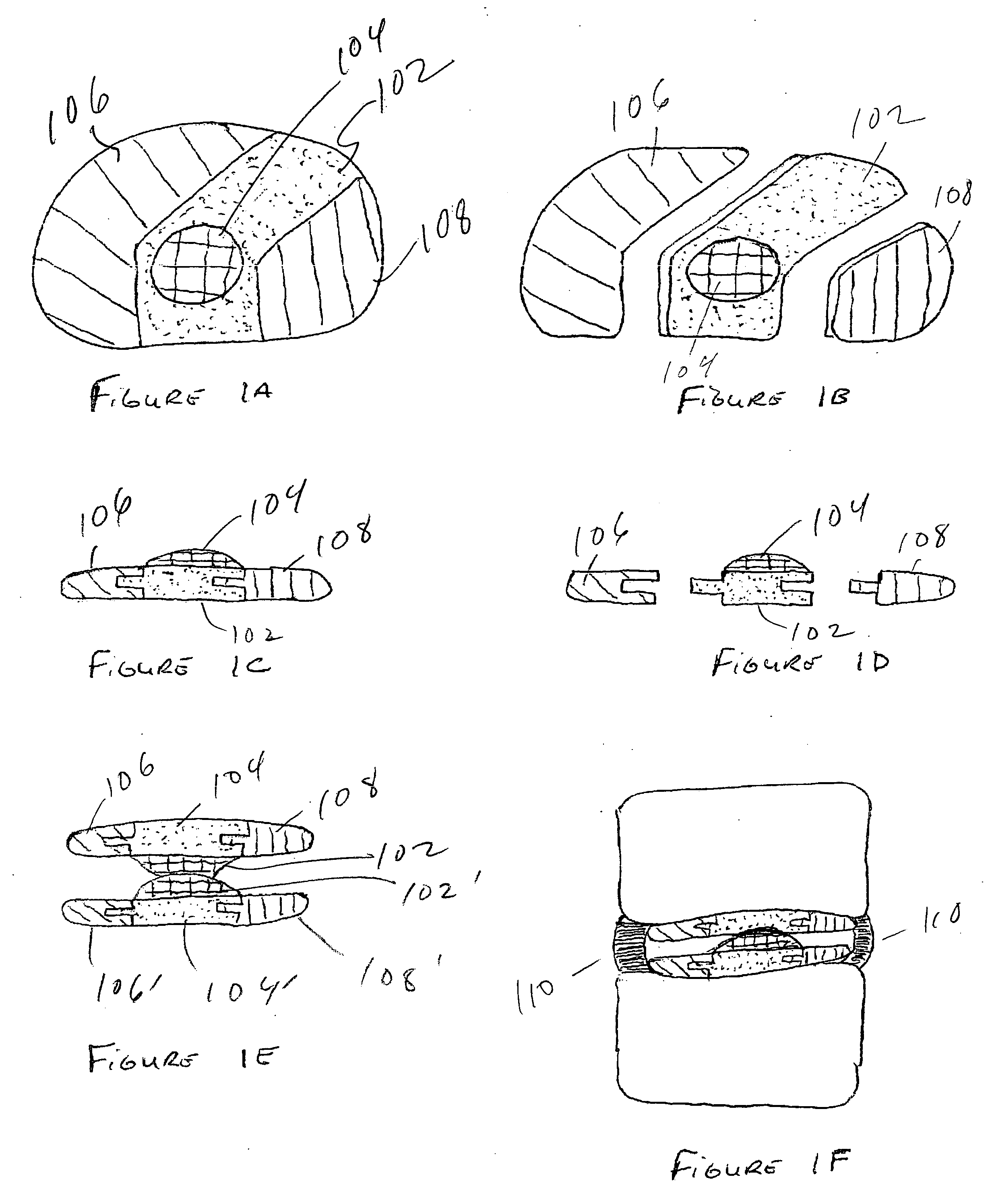
[0047]FIG. 1A is a view of the top of the articulating side of preferred embodiment of the invention. The assembled component may represent the top or bottom half of a disc spacer. The center component 102 contains a spherical articulating surface 104. The spherical articulating surface may be concave, convex, flat, or some combination thereof depending upon the opposing articulating surface. Separate components 106, 108 are located on either side of the component with the articulating surface.

[0048]FIG. 1B is an exploded view of the top of the embodiment of the invention drawn in FIG. 1A. FIG. 1C is a lateral view of the embodiment of the invention drawn in FIG. 1A. FIG. 1D is an exploded lateral view of the embodiment of the invention drawn in FIG. 1B. FIG. 1E is a lateral view of an assembled disc spacer in the preferred embodiment of the invention. The device is made of six components.

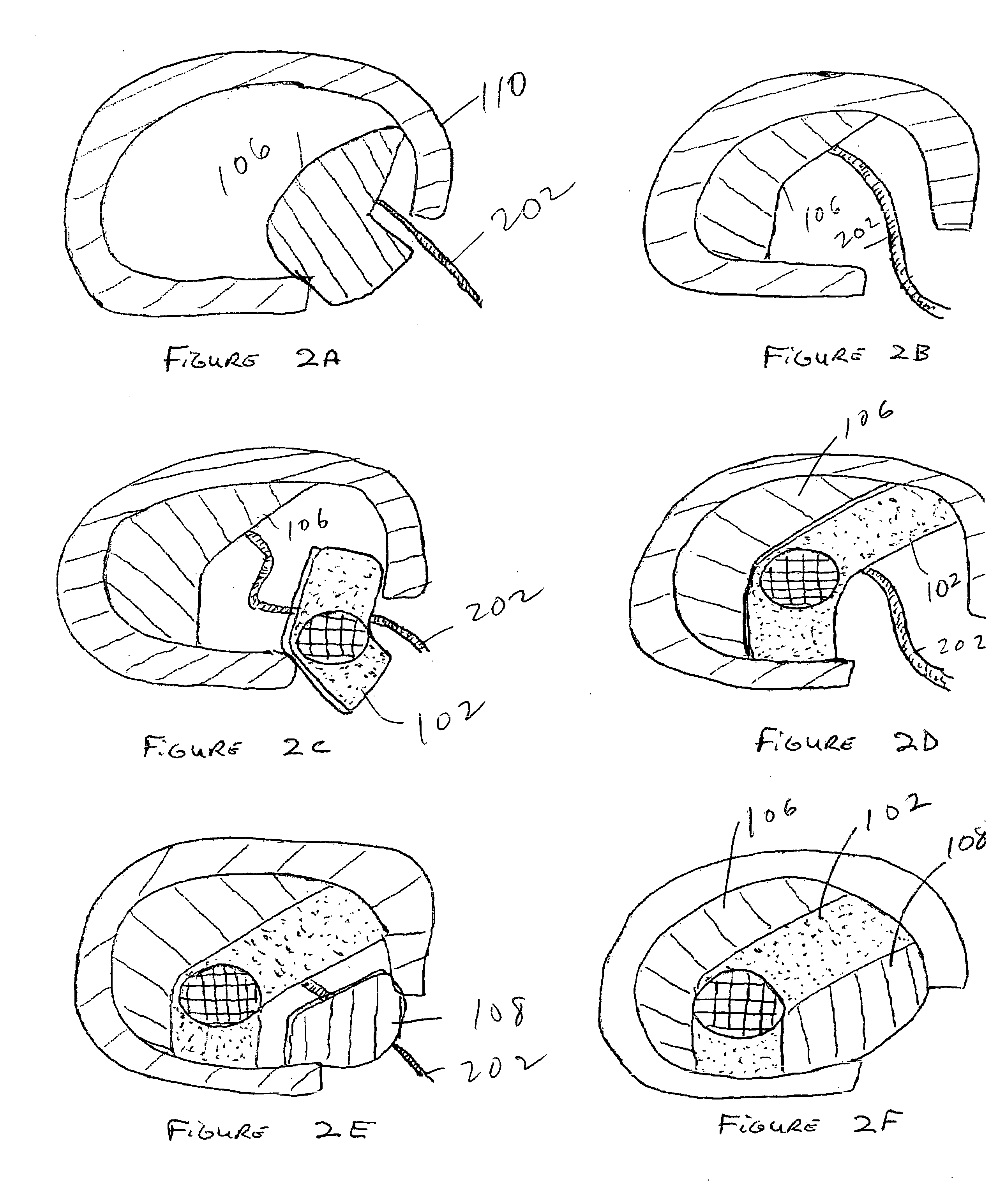
[0049]FIG. 1F is a coronal cross section of the spine and the embodiment of the invention dra...


PUM


Abstract

Disc spacers (DS) are assembled within a disc space, allowing them to be inserted through smaller openings in the Annulus Fibrosus (AF). The large size of the assembled DS decreases the pressure on the vertebral endplates. Embodiments of the invention may be used in the cervical, thoracic, or lumbar spine. The DS may be inserted through an anterior, lateral, or posterior approach to the spine using annulus preserving techniques. The devices are preferably made of biocompatible materials such as titanium, chrome cobalt, and ceramic. Alternative materials, including materials with shape memory properties, such as Nitinol, may be used to form one or more components of the device.

Description

REFERENCE TO RELATED APPLICATION [0001] This application is a continuation-in-part of U.S. patent application Ser. No. 10 / 422,282, filed Apr. 24, 2003, which claims priority from U.S. Provisional Patent Application Ser. No. 60 / 375,212, filed Apr. 24, 2002, the entire content of both of which are incorporated herein by reference.FIELD OF THE INVENTION [0002] This invention relates generally spine surgery and, in particular, to assembled disc spacers. BACKGROUND OF THE INVENTION [0003] Premature or accelerated disc degeneration is known as degenerative disc disease. A large portion of patients suffering from chronic low back pain are thought to have this condition. As the disc degenerates, the nucleus and annulus functions are compromised. The nucleus becomes thinner and less able to handle compression loads. The annulus fibers become redundant as the nucleus shrinks. The redundant annular fibers are less effective in controlling vertebral motion. The disc pathology can result in: 1) ...

Claims


Application Information

Patent Timeline
Patent Type & Authority Applications(United States)
IPC IPC(8): A61F2/44A61F2/00A61F2/30A61F2/38
CPCA61F2/38A61F2310/00179A61F2002/30092A61F2002/30125A61F2002/302A61F2002/30245A61F2002/30528A61F2002/30563A61F2002/30649A61F2002/30878A61F2002/443A61F2210/0014A61F2220/0025A61F2230/0008A61F2230/0065A61F2230/0071A61F2310/00017A61F2310/00023A61F2310/00029A61F2/4425
Inventor FERREE, BRET A.TOMPKINS, DAVID
Owner FERREE BRET A
Why Eureka
Try Eureka