Socket connection test modules and methods of using the same

a test module and socket connection technology, applied in the direction of electric connection testing, measurement devices, instruments, etc., can solve problems such as failure to boot altogether, processor malfunction, reliability problems,

Inactive Publication Date: 2006-01-12
INTEL CORP
View PDF6 Cites 11 Cited by
  • Summary
  • Abstract
  • Description
  • Claims
  • Application Information

AI Technical Summary

Problems solved by technology

The inspection of the socket connections to a PCB is valuable because open solder joints, broken pins, springs, or other poor connections on any of the signal connections may result in the processor malfunctioning, or failing to boot altogether.
Openings on the power and ground connections may cause the processor to malfunction under a heavy load, cause hot spots due to excessive current in the connected power and ground pins, or cause reliability issues over time at the customer end.
Human visual inspection of the solder joints within a BGA socket or the conductive traces within a LGA socket is not possible.
By this technique, poor connections and traces within the PCB and socket can be detected.
But, the Testjet™ technique has limitations in its ability to detect traces (or pins) within the PCB that are tied, such as the commonly tied power or ground traces.
The TestJet™ can thus fail to detect broken traces or open solder joints on tied traces.
The TestJet™ also has difficultly detecting weak signals due to shorter signal propagation paths in current generations of sockets.
Because of this requirement, the FET TCT must have a large footprint that can cause fixture design issues and difficulty of use.
As the number of traces increases and devices are further scaled down, the FET TCT will become even larger and more difficult to use.
Additionally, the FET TCT is a power-up test that is only compatible with an in-circuit tester and not an MDA tester type that is widely used by Far East board manufacturing.
The FET TCT is also not easily compatible with a land grid array (LGA) CPU because an LGA is typically quite fragile and a bulky FET TCT test module could cause significant harm.

Method used


Image

  • Socket connection test modules and methods of using the same
  • Socket connection test modules and methods of using the same
  • Socket connection test modules and methods of using the same

Examples


Embodiment Construction

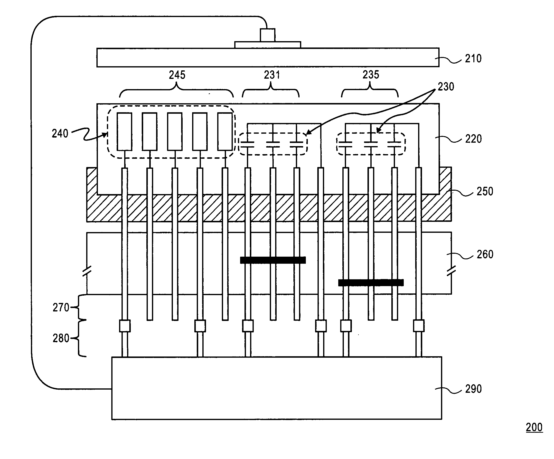
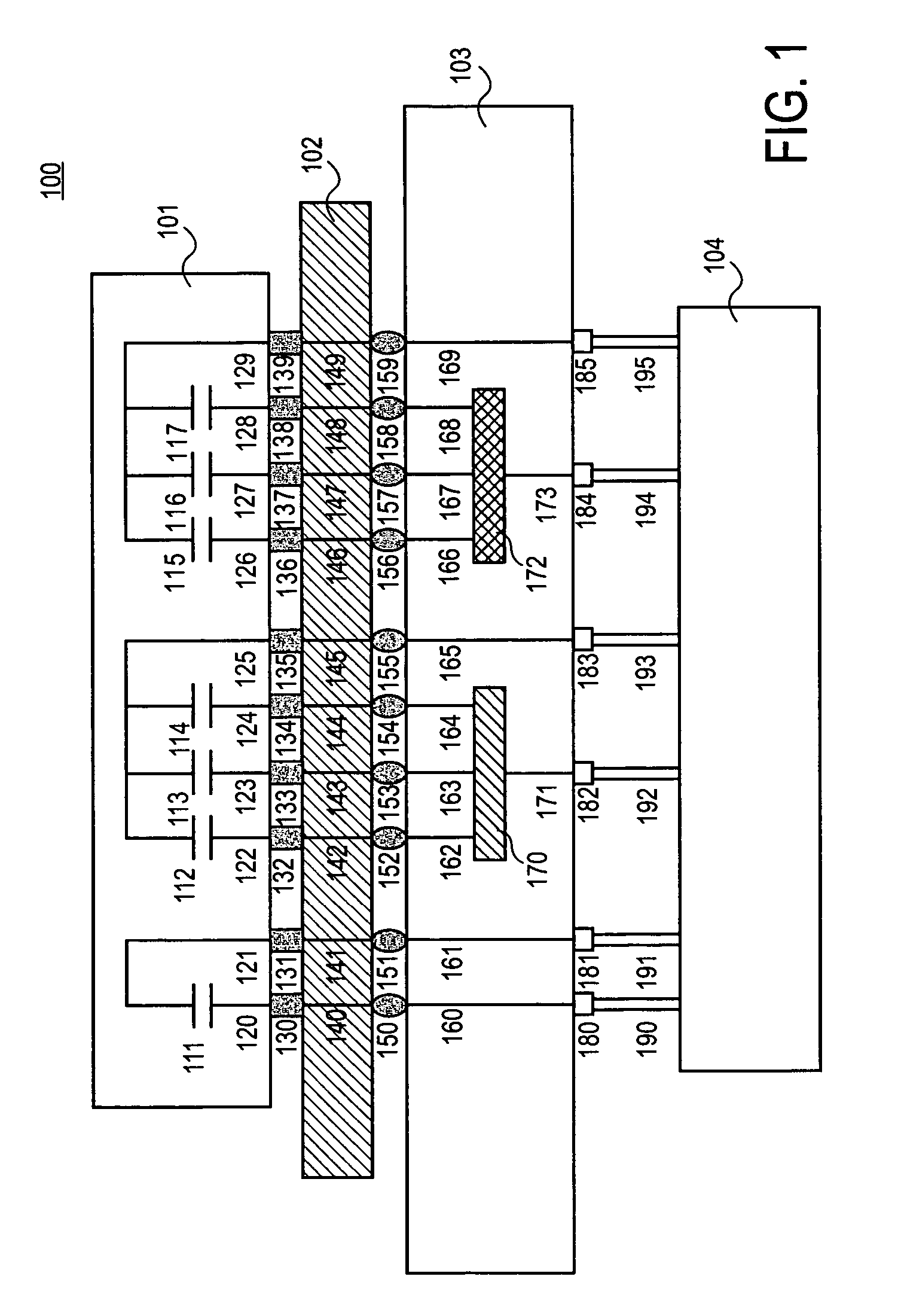
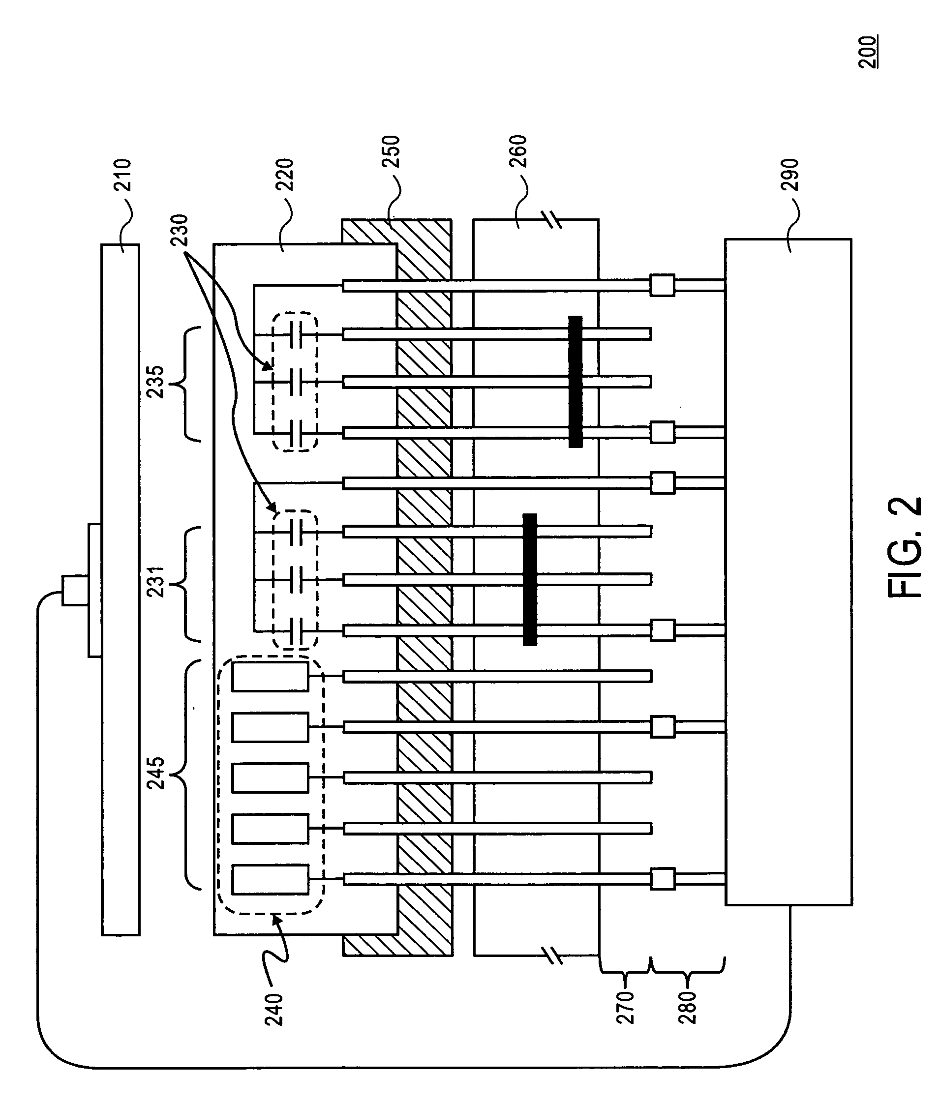
[0014] Embodiments of the present invention provide methods and devices employing capacitors for testing the integrity of the electrical connections between a printed circuit board (PCB) and a socket of a device as well as the traces within the PCB and socket. In the following description, numerous specific details are set forth. One of ordinary skill in the art, however, will appreciate that these specific details are not necessary to practice embodiments of the invention. While certain exemplary embodiments of the invention are described and shown in the accompanying drawings, it is to be understood that such embodiments are merely illustrative and not restrictive of the current invention, and this invention is not restricted to the specific constructions and arrangements shown and described because modifications may occur to those ordinarily skilled in the art.

[0015] Described herein are embodiments of test modules, systems, and methods employing capacitors for the testing of th...


PUM


Abstract

Test modules, systems, and methods employing capacitors for the testing of the solder joint connections between a printed circuit board (PCB) and a socket of a device are presented in embodiments of the current invention. A test module having capacitors in parallel, and in particular embedded capacitors, can be used to test tied traces and their solder joint connections by measuring the total capacitance of the capacitors. Embodiments of the current invention present no-power tests that can be used with a variety of testing platforms and test fixtures, such as in-circuit testing (ICT) and manufacturing defect analysis (MDA.) Additionally, the test module can be used with a variety of sockets, such as a ball grid array, a pinned grid array, and a land grid array.

Description

BACKGROUND OF THE INVENTION [0001] 1. Field of the Invention [0002] Embodiments of the present invention relate to the field of testing electrical connections and traces of an electronic device and a printed circuit board. More particularly, embodiments of the present invention relate to the use and integration of parallel capacitors with external or embedded capacitors in a test module to test the connections between a printed circuit board, or a motherboard, and a device socket. [0003] 2. Discussion of Related Art [0004] It is valuable to be able to test the electrical connections between the sockets of electronic devices and a printed circuit board (PCB) or motherboard, as well as the integrity of the traces within the testing equipment, socket, and PCB. The inspection of the socket connections to a PCB is valuable because open solder joints, broken pins, springs, or other poor connections on any of the signal connections may result in the processor malfunctioning, or failing to ...

Claims


Application Information

Patent Timeline
Patent Type & Authority Applications(United States)
IPC IPC(8): G01R31/02G01R1/073G01R31/04G01R31/28
CPCG01R1/07328G01R31/2896G01R31/2806G01R31/048G01R31/71
Inventor HO, SEE CHENGTOH, TEIK SEANTAN, TZYY HAW
Owner INTEL CORP
Why Eureka
Try Eureka