Color liquid crystal display device

Inactive Publication Date: 2006-01-12
ALPS ALPINE CO LTD
View PDF0 Cites 67 Cited by
  • Summary
  • Abstract
  • Description
  • Claims
  • Application Information

AI Technical Summary

Benefits of technology

[0016] It is another object of the invention to provide a color liquid crystal display device employing a field sequential display method without requiring color filters, which is capable of decreasing the number of source wiring lines for pixel driving and decreasing the number of wiring lines surrounding a gate driver and hence reducing the area required for the wiring lines

Problems solved by technology

However, the current TN-TFT-type LCD has technical difficulty in achieving the high brightness and high-speed response.
For example, one of reasons for the difficulty in achieving the high brightness is that color filters requisite for color display in the TN-TFT-LCD wastefully absorb most of light emitted from a light source provided in the liquid crystal display device.
This leads to miniaturization of a circuit for controlling the liquid crystal display and to increase in the number of wiring lines for driving minute thin film transistors.
In addition, in the Japanese Unexamined Patent Application Publication No. 11-14988, since three red, blue and green cold cathode fluorescent tubes are used to perform the color display by the field sequential method, power consumption is great and thus there is a need of a heavy cell having high capacity.
Therefore, it is difficult to implement a thin and lightweight display device.
Accordingly, the

Method used


Image

  • Color liquid crystal display device
  • Color liquid crystal display device
  • Color liquid crystal display device

Examples


first embodiment

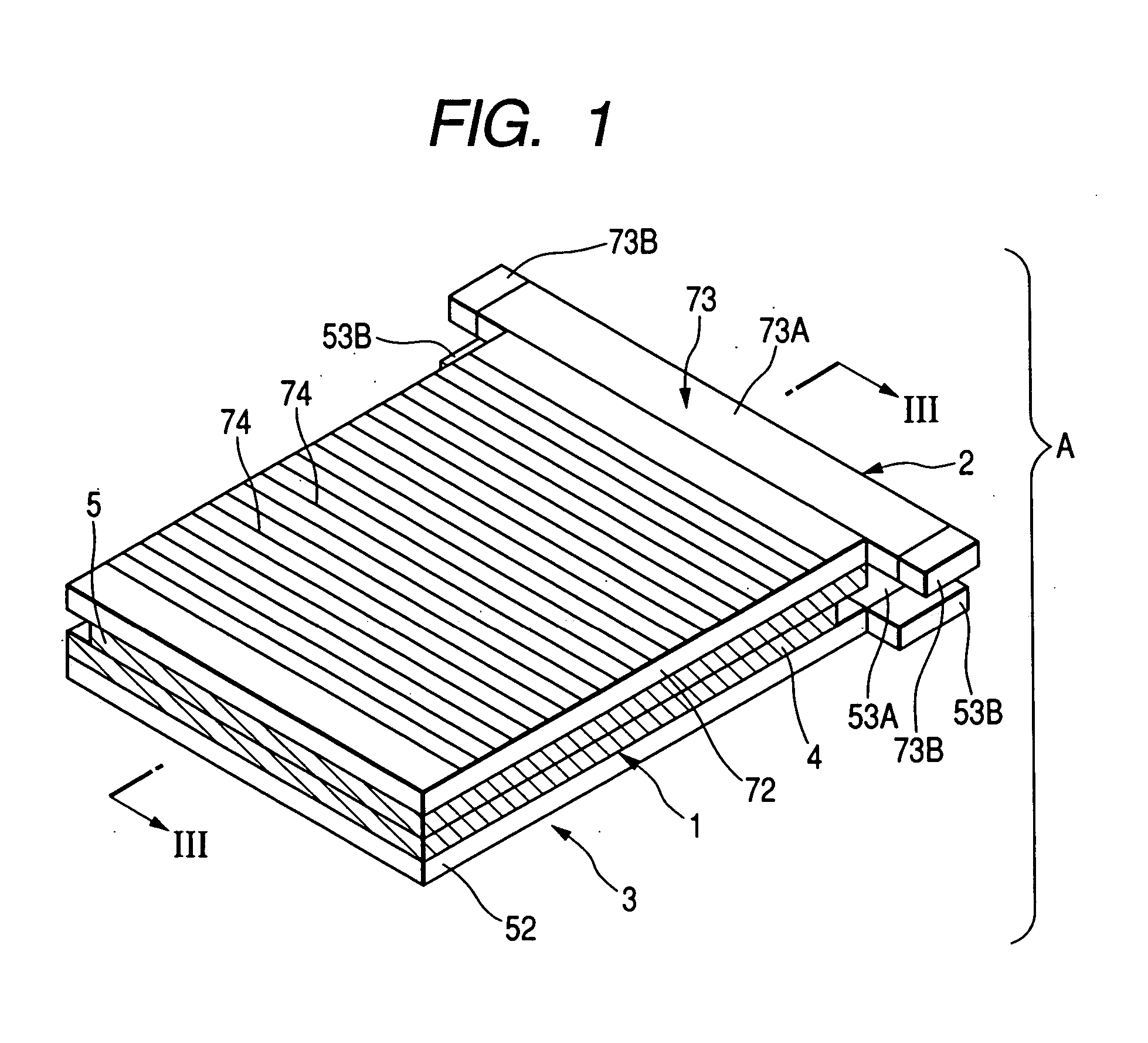
[0040]FIG. 1 is a perspective view of the entire configuration of a liquid crystal display device according to a first embodiment of the invention. A liquid crystal display device A includes a transflective liquid crystal display panel 1, a frontlight 2 disposed at a front side of the liquid crystal display panel 1 to emit light from a surface of the liquid crystal display panel 1, and a backlight 3 disposed at a back side of the liquid crystal display panel 1 to emit light from the back side of the liquid crystal display panel 1. Hereinafter, structures of the liquid crystal display panel 1, the backlight 3, and the frontlight 2 and a structure for driving these elements and for displaying images will be described.

[0041] Liquid Crystal Display Panel

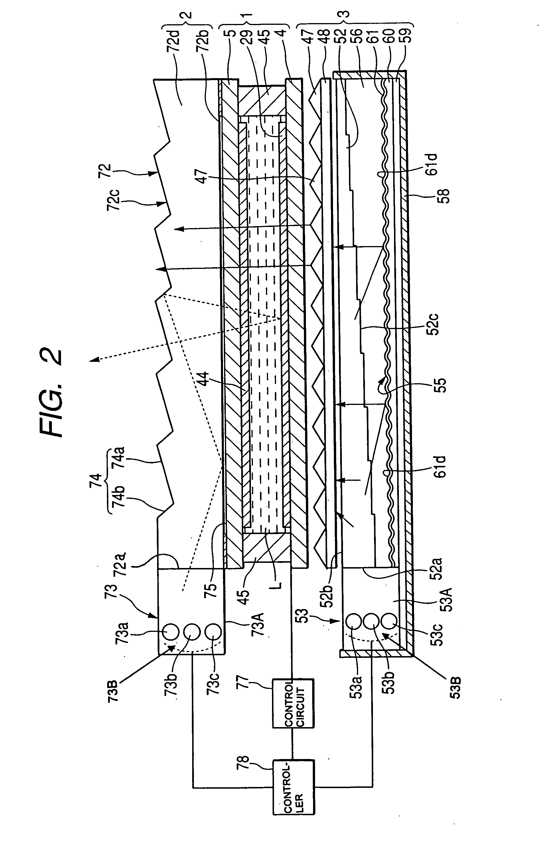
[0042] As shown in FIGS. 2 and 3, the liquid crystal display panel 1 includes an active matrix substrate (one substrate) 4 on which switching elements are formed, a counter substrate (the other substrate) 5 opposite to the active matri...

second embodiment

[0114]FIG. 13 is an exploded sectional view of a structure of a second embodiment of a liquid crystal display panel applied to the liquid crystal display device according to the invention.

[0115] A liquid crystal display panel 91 of the second embodiment is mostly similar to the liquid crystal display panel 1 described with reference to FIG. 3, except a structure of the pixel electrode. Therefore, the same elements as the liquid crystal display panel 1 described with reference to FIG. 3 are denoted by the same reference numerals, and explanation thereof will be omitted.

[0116] In the structure of the second embodiment, an interlayer insulating layer 92 is formed to cover a thin film transistor T and a surface of a substrate 6, and a transparent electrode 93 having a function corresponding to the transparent electrode 19 in the structure of the first embodiment is formed on the interlayer insulating layer 92. The transparent electrode 93 is connected to a source electrode 17 of the t...


PUM


Abstract

A color liquid crystal display device includes a transflective liquid crystal display panel, a frontlight arranged on a surface of the liquid crystal display panel, the frontlight including a front-side light source for emitting light having three primary colors, a backlight arranged on a back side of the liquid crystal display panel, the backlight including a back-side light source for emitting light having three primary colors, a controller for controlling the front-side light source and the back-side light source such that light emitted from the front-side light source and the back-side light source is irradiated onto the liquid crystal display panel as alternating light, and a control circuit for controlling display of the liquid crystal display panel in synchronization with the alternating light.

Description

BACKGROUND OF THE INVENTION [0001] 1. Field of the Invention [0002] The present invention relates to a color liquid crystal display device, which is capable of displaying bright color and allowing both of reflection and transmission displays without using color filters. [0003] 2. Description of the Related Art [0004] Liquid crystal display technologies have been developed with bipolarization divided between a large-sized liquid crystal display device allowing large screen display such as a television picture and a small-sized liquid crystal device applied to a mobile phone, a personal digital assistant (PDA) and the like. [0005] The large-sized liquid crystal display device requires the wide viewing angle, high contrast and high color reproductivity, as well as high-speed response at the time of reproducing moving pictures. On the other hand, in the small-sized liquid crystal display device employed for the mobile phone and the like, a thin film transistor (TFT) type liquid crystal ...

Claims


Application Information

Patent Timeline
IPC IPC(8): G09G3/36G09G3/34
CPCG02F1/133555G02F1/1336G02F2001/133616G09G2310/0235G09G3/3406G09G3/3611G09G2300/0456G02F2001/133622G02F1/133622G02F1/133616G02F1/133G02F1/1335
Inventor YASUOKA, YOZOKANO, MITSURU
Owner ALPS ALPINE CO LTD
Why Eureka
Try Eureka