Image forming apparatus

a technology of forming apparatus and forming cylinder, which is applied in the direction of electrographic process apparatus, instruments, optics, etc., can solve the problems of inability to reduce the difference between the actual toner consumption property and the toner property calculated by the pixel count, and inability to accurately calculate toner consumption. to achieve the effect of accurately calculating toner consumption, optimizing toner consumption properties, and optimizing toner consumption

Inactive Publication Date: 2006-01-12
SHARP KK
View PDF2 Cites 17 Cited by
  • Summary
  • Abstract
  • Description
  • Claims
  • Application Information

AI Technical Summary

Benefits of technology

[0035] With an image forming apparatus having this sort of configuration, even when actual toner consumption properties have changed due to individual differences and toner life, it is possible to rewrite the weighting coefficient of a weighting coefficient ta

Problems solved by technology

However, in conventional electrophotographic apparatuses such as digital copy machines, there were the following problems.
Therefore, there is the problem that the toner consumption cannot be accurately calculated from the sum value of the pixel count after weighting.
However, when the toner consumption properties change from curve D shown by the solid line in FIG. 10 to the broken line show

Method used


Image

  • Image forming apparatus
  • Image forming apparatus
  • Image forming apparatus

Examples


Embodiment Construction

[0046] Below follows a description of an embodiment of the present invention, with reference to the accompanying drawings. The embodiment described below is one specific example of the present invention, and does not limit the technical scope of the present invention.

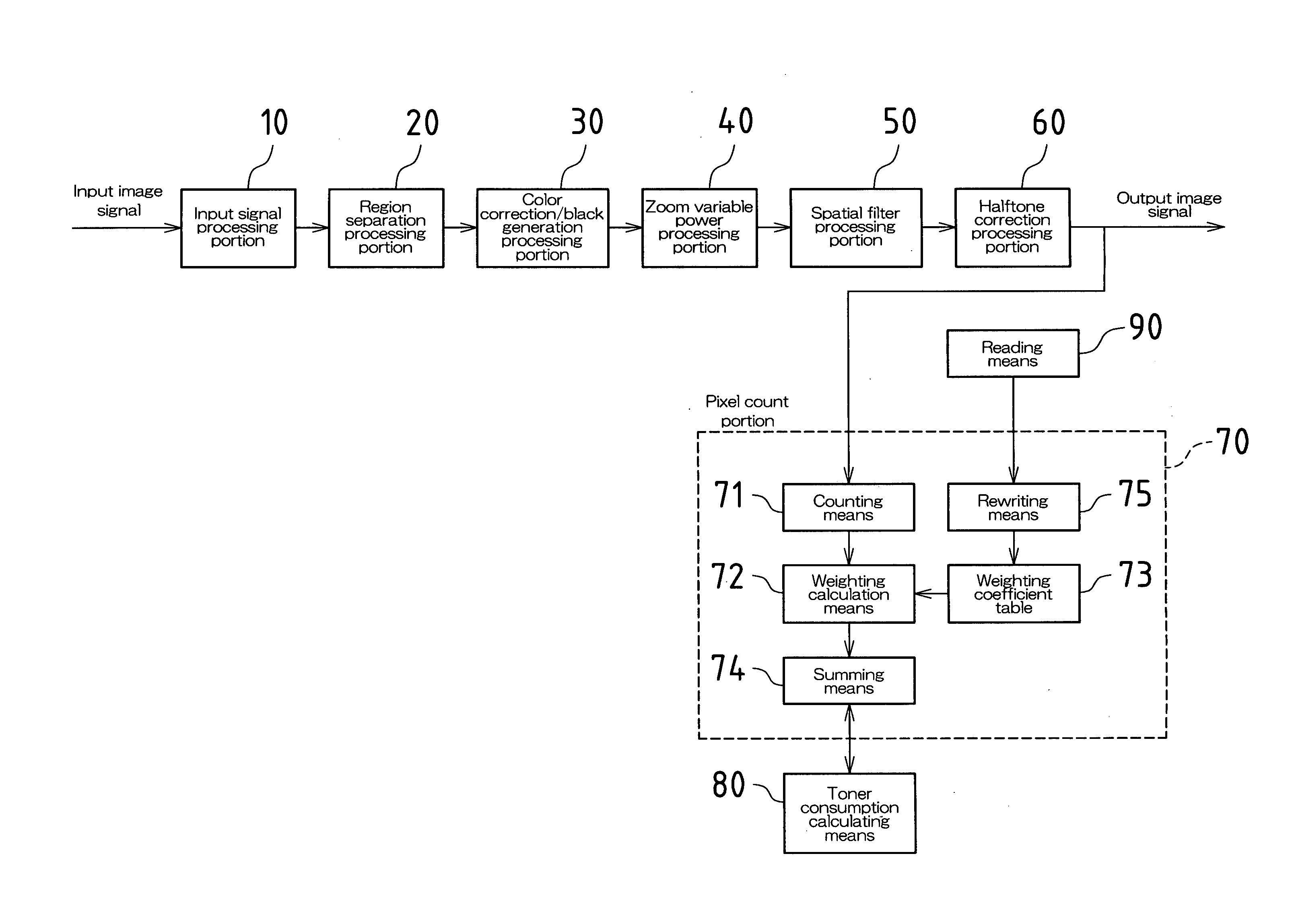
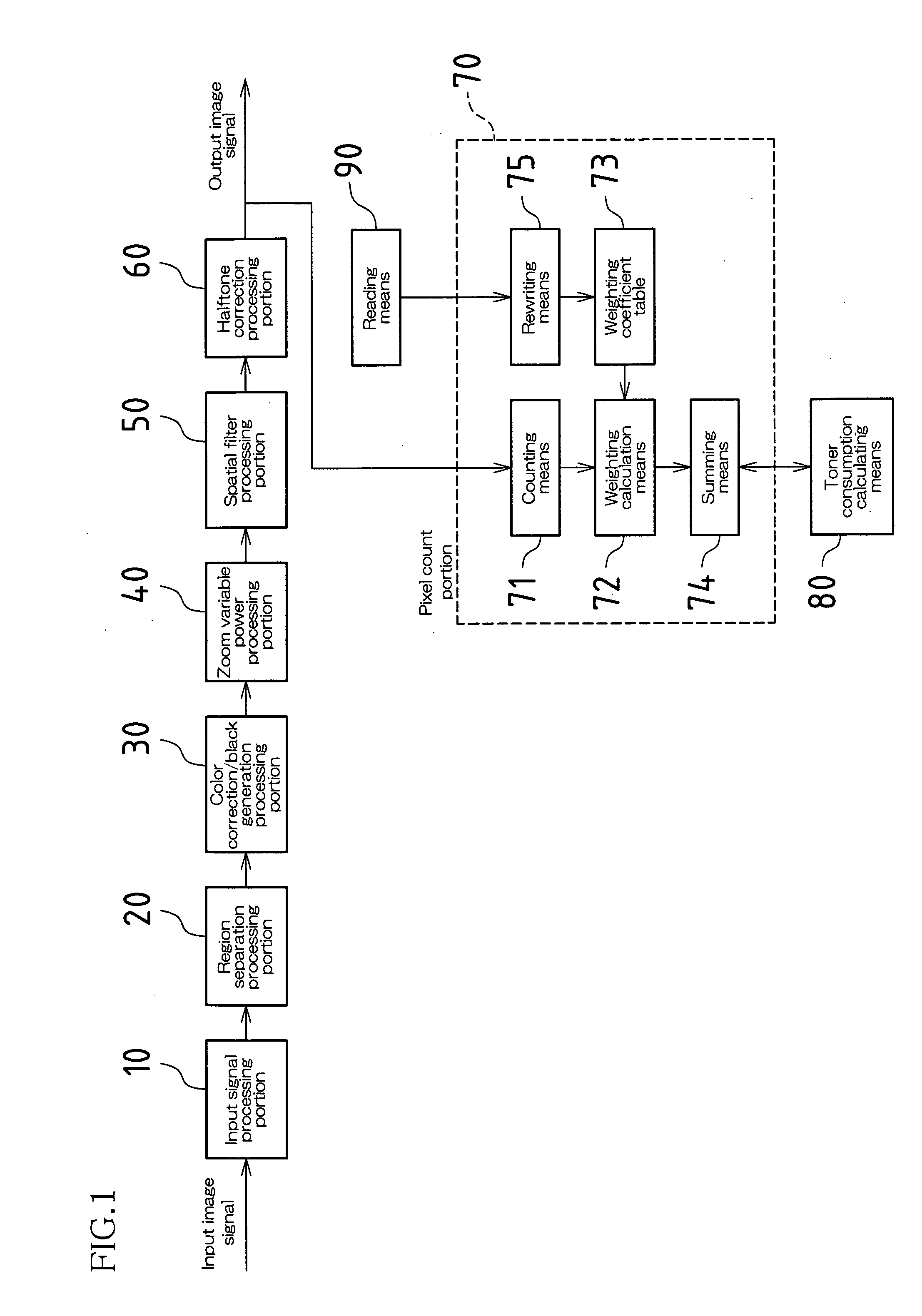
[0047]FIG. 1 is a control block diagram showing the image processing in the image forming apparatus (digital electrophotographic apparatus) associated with an embodiment of the present invention. As shown in FIG. 1, this digital electrophotographic apparatus includes an input signal processing portion 10, a region separation processing portion 20, a color correction / black generation processing portion 30, a zoom variable power processing portion 40, a spatial filter processing portion 50, a halftone correction processing portion 60, a pixel counting portion 70, and a toner consumption calculating portion (toner consumption calculating means) 80. In the digital electrophotographic apparatus, a digitally input image sign...


PUM


Abstract

One embodiment is an image forming apparatus that digitally performs image processing and correction processing of image information, and calculates toner consumption by performing a pixel count of the input multi-level image includes a counting portion that counts, pixel by pixel, the input signal levels of an input multi-level image; a weighting coefficient table that stores weighting coefficients corresponding to the input signal levels; a weighting calculation portion that obtains from the weighting coefficient table weighting coefficients corresponding to the input signal levels and performs weighting of each pixel when counting the input signal levels with the counting portion; and a rewriting portion that rewrites the weighting coefficients stored in a weighting coefficient table.

Description

CROSS REFERENCE TO RELATED APPLICATION(S) [0001] This application claims priority under 35 U.S.C. § 119(a) to Japanese Patent Application No. 2004-199647, filed on Jul. 6, 2004, the entire contents of which are hereby incorporated by reference. BACKGROUND OF THE INVENTION [0002] 1. Field of Invention [0003] The present invention relates to image forming apparatuses such as copy machines, laser beam printers, facsimile apparatuses, and the like using an electrophotographic method wherein image processing and correction processing of image information is digitally performed. [0004] 2. Related Art [0005] Generally, with image processing in electrophotographic apparatuses such as digital copy machines, a digital image signal input by an image input apparatus such as a scanner is output as an output image signal after such digital signal processing as input signal processing, region separation processing, color correction processing, black generation processing, zoom variable power proce...

Claims


Application Information

Patent Timeline
IPC IPC(8): H04N1/46
CPCG03G15/553H04N1/00002H04N1/00015H04N1/0005G03G15/556H04N1/40006H04N1/4078H04N2201/0082H04N1/00068
Inventor IMAGAWA, SHINJIKAWANO, HIROSHI
Owner SHARP KK
Why Eureka
Try Eureka