Optical apparatus

a technology of optical equipment and optical axis, which is applied in the direction of camera focusing arrangement, printers, instruments, etc., can solve the problems of difficult to know whether the defocus is caused by front focus or rear focus, difficult to perform focus detection, and inconvenient methods, etc., to achieve fast focusing operation and accurate focusing

Inactive Publication Date: 2006-01-12
CANON KK
View PDF7 Cites 46 Cited by
  • Summary
  • Abstract
  • Description
  • Claims
  • Application Information

AI Technical Summary

Benefits of technology

[0012] It is an object of the present invention to provide an optical appa

Problems solved by technology

The focus detection in the contrast AF method, however, can only cover a narrow range of defocus amounts, so that the focus detection is difficult to perform when the image is significantly out of focus.
In addition, since it takes a long time to move the focusing lens from the infinity end to the closest end in order to search for an in-focus position, the method is inappropriate for a system requiring fast operation and image-taking of a subject who moves quickly.
Moreover, the high-frequency component of a luminance signal is not changed largely at positions away from an in-focus position, so that it is difficult to know whether defocus is caused by front focus or rear focus.
The focus detection in the phase difference detection AF method has the problem of involving a dead zone in its focus detection area although it can cover a wide range of defocus amounts.
Also, since the movement

Method used


Image

  • Optical apparatus
  • Optical apparatus
  • Optical apparatus

Examples


embodiment 1

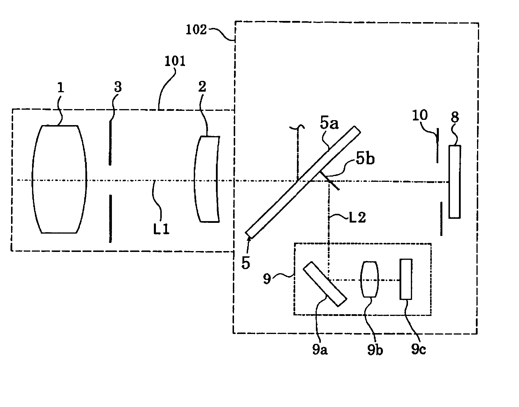
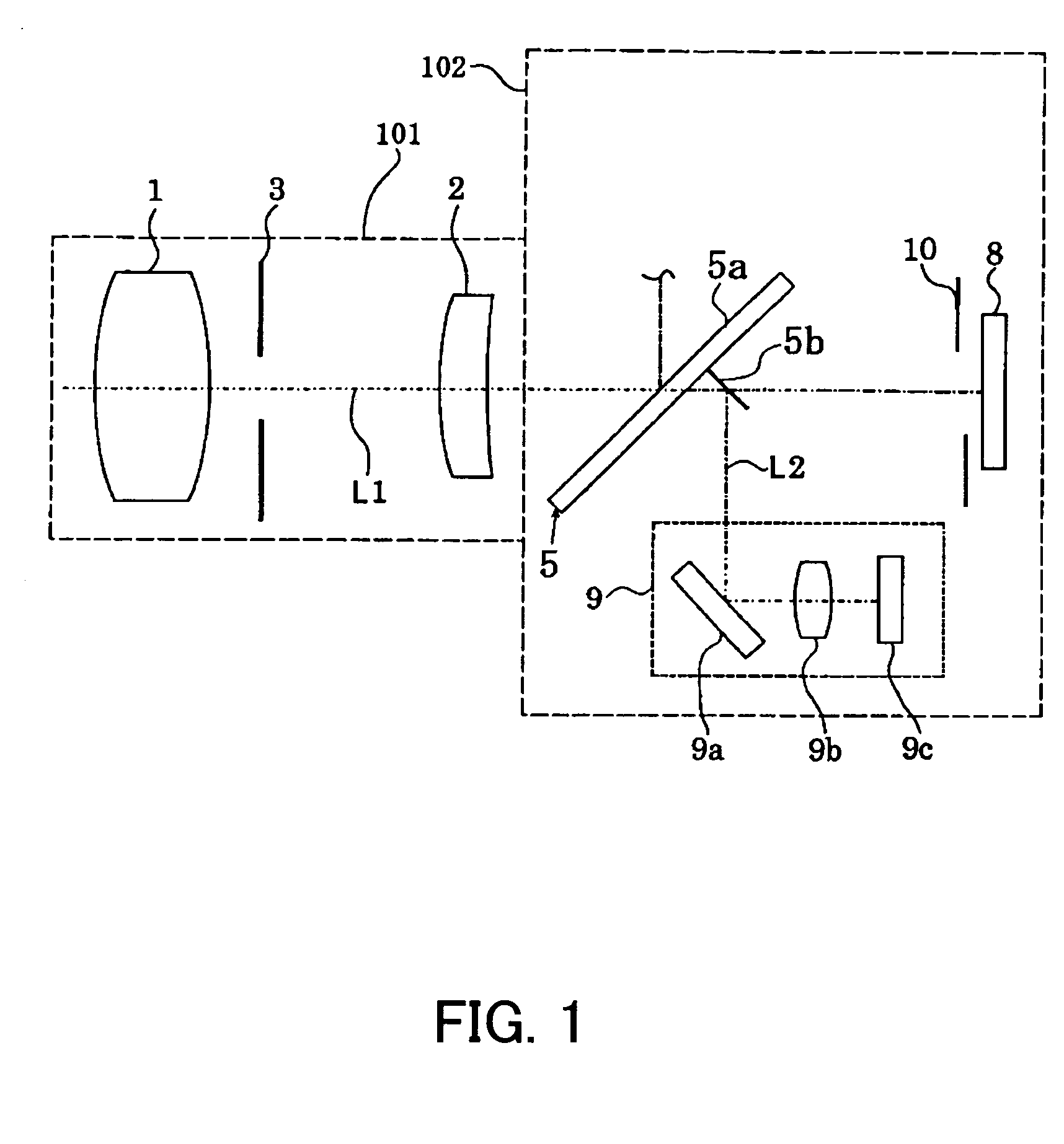
[0031]FIG. 1 shows the structure of main components of a camera system (an optical apparatus) which is Embodiment 1 of the present invention. The camera system of Embodiment 1 has a camera body 102 and a lens apparatus 101 which is mounted on the camera body 102. While Embodiment 1 will be described on the assumption that the camera system is an optical apparatus in which the lens apparatus 101 is removably mounted on the camera body 102, for example a single-lens reflex camera, it may be an optical apparatus integral with a lens.

[0032] Reference numerals 1 and 2 show image-taking lenses. Specifically, the image-taking lens 1 is a zoom lens which can be moved in the direction of an optical axis L to change the focal length of an image-taking optical system. The image-taking lens 2 is a focus lens which is moved in the direction of the optical axis L to adjust focus. Each of the lenses may be formed of a single or a plurality of lenses. Reference numeral 3 shows an aperture serving ...

embodiment 2

[0083]FIG. 10 illustrates Embodiment 2 of the present invention. FIG. 10 is a flow chart showing AF control in a camera system of Embodiment 2. Since a camera body 102, a lens apparatus 101, a circuit structure and the like are the same as those in Embodiment 1, description thereof is omitted.

[0084] The focal depth is larger as the focal length is smaller, and the focal depth is smaller as the focal length is larger, so that precise AF control needs to be performed when the focal length is large. Thus, in the camera system of Embodiment 2, the AF control is performed on the basis of a focal length detected by a focal length detection circuit 47.

[0085] First, the focal length detection circuit 47 detects the position of the zoom lens 1, and calculates the focal length based on the position of the zoom lens 1 and outputs the calculated focal length to a system controller 46 as focal length information.

[0086] If it is determined that the focal length information input to the system ...

embodiment 3

[0092]FIG. 11 shows the structure of main components of a camera system (an optical apparatus ) which is Embodiment 3 of the present invention. The camera system of Embodiment 3 has some of the components different from those of the camera system (the optical apparatus ) described in FIG. 1. The common components are designated with the same reference numerals and description thereof is omitted. Embodiment 3 is characterized by a mirror 105.

[0093] Specifically, when the camera system is in an OVF (Optical View Finder) state as a first state, a half mirror 105a transmits part of luminous flux passing through image-taking lenses 1 and 2 toward an image plane and reflects the remaining luminous flux toward a viewfinder optical system, not shown, provided in a camera body 102. A sub mirror 105b disposed closer to the image plane than the half mirror 105a reflects the luminous flux transmitted through the half mirror 105a toward a focus detection unit 9 while the camera is not taking an...


PUM


Abstract

An optical apparatus which achieves fast focusing operation and allows accurate focusing is disclosed. The optical apparatus includes a first focus detector which detects a focus state on a subject, a second focus detector which detects a focus state on the subject in a detection method different from a detection method of the first focus detector, and a controller which has a function of detecting whether or not the subject is a moving body and a function of performing focus control of an image-taking optical system in a first sequence in which at least one of the first and second focus detectors is used and a second sequence in which at least the other of the focus detectors is used. The controller preferentially uses one of the first and second sequences depending on the result of the detection with the moving body detecting function.

Description

BACKGROUND OF THE INVENTION [0001] The present invention relates to an optical apparatus such as a camera, and more specifically, to focusing operation and control thereof. [0002] In recent years, so-called digital cameras have been prevalent in which an image-taking optical system focuses a subject image onto a semiconductor image-pickup device (such as a CCD sensor and a CMOS sensor) for conversion into an electric signal and the resulting image information is recorded on a recording medium such as a semiconductor memory and a magnetic disk. [0003] The electronic camera of this type is equipped with an auto-focus (AF) function of controlling image-taking conditions in order to automatically focus on a subject image. As methods of the auto-focus control, a contrast AF method and a phase difference detection AF method are adopted. [0004] Known contrast AF methods include a climbing method in which a focus lens is moved in a direction in which the high-frequency component of a lumina...

Claims


Application Information

Patent Timeline
IPC IPC(8): G03B13/00G02B7/28G02B7/34G02B7/36H04N5/232
CPCH04N5/23212G02B7/102H04N23/672H04N23/673
Inventor ITO, KENJI
Owner CANON KK
Why Eureka
Try Eureka