Methods and apparatus for sensing parameters of air flows

a technology of air flow and sensor, applied in the direction of liquid fuel engines, instruments, machines/engines, etc., can solve the problems of significant negative effect of flowstream itself, strength and reliability, and potential steep tradeoffs between measuring attributes,

Active Publication Date: 2006-01-12
THE UNITED STATES OF AMERICA AS REPRESENTED BY THE SECRETARY OF THE NAVY
View PDF16 Cites 3 Cited by
  • Summary
  • Abstract
  • Description
  • Claims
  • Application Information

AI Technical Summary

Benefits of technology

[0010] Some aspects of the present invention therefore provide a vane assembly that includes a vane having a main axis, a first passageway within the vane substantially parallel to the main axis, and a second passageway aligned with the first passageway. The vane has a window portion between the first passageway and the second passageway. The vane assembly also includes a sensor inserted in the first passageway and having a portion held in place in the second passageway, wherein a portion of the sensor is exposed in the window portion of the vane.

Problems solved by technology

A potentially steep tradeoff exists between measuring attributes of a flowstream, interfering with the flowstream itself, and sensor strength and reliability.
Thus, mounting a separate sensor in a flowstream can have a significant negative effect on the flowstream itself.
Enclosing a sensor in the body of a flow vane always results in the sensor signal having a longer time constant than that of an unenclosed sensor.
This configuration may not be effective in an application with highly dynamic secondary properties as described above.
It is difficult or impossible to remove or install the sensor intact in this configuration without making the sensor flexible.
However, it may not be desirable for a sensor to be flexible in a very hot and / or fast flow stream environment, as durability of the exposed portion of the sensor may be reduced.
Axial removal of the flow vane is also complicated by protrusion of the sensor element, which is typically mounted substantially orthogonal to a wall surface of the flow vane.
However, the exposed sensor body can disrupt airflow over the entire length of the sensor lead element.
A strong tradeoff exists between reliability and the magnitude of the disruption of the primary flow because more reliable sensors are larger in size and more likely to disrupt the primary flow.
Usually, this configuration is used in development studies due to low sensor reliability.
In addition, vane removal may be difficult due to the external modification.
Although each of these sensor configurations provides adequate sensor information, it is clear that the tradeoffs involved for each may not be desirable for particular sensor / vane flow measurement applications.
For example, these configurations may not minimize airflow disruption while simultaneously maintaining or improving reliability and time constant of either the sensor element or of the flow vane.

Method used


Image

  • Methods and apparatus for sensing parameters of air flows
  • Methods and apparatus for sensing parameters of air flows
  • Methods and apparatus for sensing parameters of air flows

Examples


Embodiment Construction

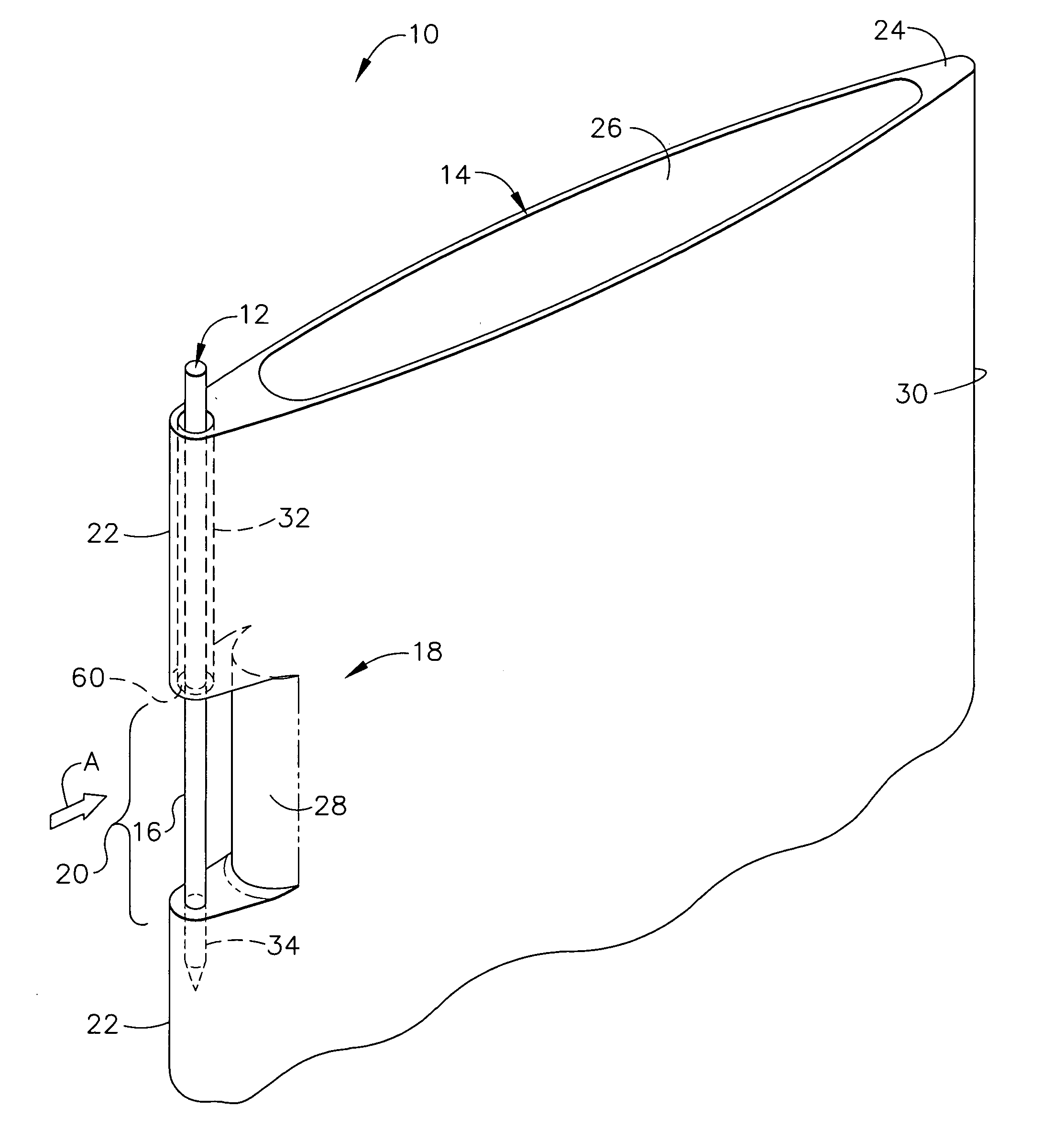
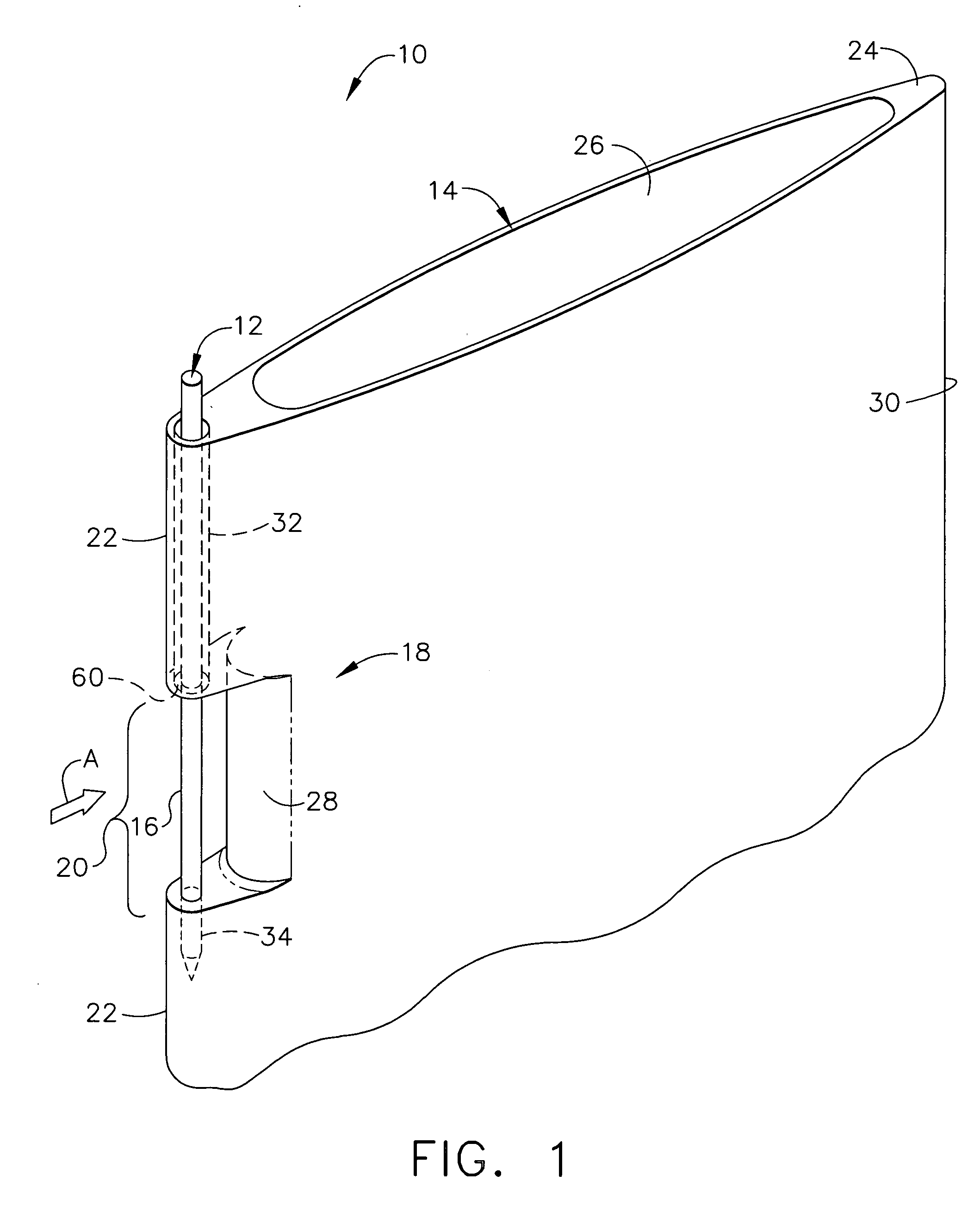
[0018] As used herein, the term “vane” should be read as encompassing vanes, wings, and airfoils unless otherwise explicitly limited.

[0019] In some configurations of the present invention and referring to vane and sensor assembly 10 shown in FIG. 1, a sensor element 12 is mounted substantially parallel to a main axis of a flow vane 14, and only a portion 16 of sensor element 12 is exposed directly to free flow stream A. Sensor 12 is inserted into a first passageway 32 having a wider diameter than sensor 12 and is pushed through until a bottom portion of sensor 12 passes through a second passageway 34 on the other side of window 20, which comprises cut-away portion 18 of vane 14. First passageway 32 and second passageway 34 are substantially parallel to the main axis of flow vane 14. In some configurations, sensor 12 is held in place by first passageway 32 and second passageway 34 and at least partly by a relatively tight fit within second passageway 34. Additionally, teeth 60 are p...


PUM

PropertyMeasurementUnit
diameteraaaaaaaaaa
physical propertyaaaaaaaaaa
temperatureaaaaaaaaaa

Abstract

A vane assembly includes a vane having a main axis, a first passageway within the vane substantially parallel to the main axis, and a second passageway aligned with the first passageway. The vane has a window portion between the first passageway and the second passageway. The vane assembly also includes a sensor inserted in the first passageway and having a portion held in place in the second passageway, wherein a portion of the sensor is exposed in the window portion of the vane.

Description

BACKGROUND OF THE INVENTION [0001] This invention relates generally to sensors and airfoils useful for various types of engines and other apparatus, and more particularly to sensors integrated into vanes. [0002] Sensors typically include two basic structures. One of these structures is an element that measures a physical attribute of interest, such as temperature or pressure, and that also provides a useful signal in either an electrical or other physical form. The other structure is an external body that simultaneously mounts, supports, and protects the sensing element. This two-part configuration allows the entire sensor to be removed and replaced independently of other local hardware in, for example, an aircraft. [0003] Some sensors are immersed in an environment of flowing fluids that have highly dynamic secondary properties (such as one or more of pressure, temperature, turbulence, conductivity, directional vector, etc.). The design of the external supporting structure of such ...

Claims


Application Information

Patent Timeline
Patent Type & Authority Applications(United States)
IPC IPC(8): F01B25/26F01D17/08G01F1/684G01K13/02
CPCG01F1/684
Inventor PONZIANI, ROBERT LOUIS
Owner THE UNITED STATES OF AMERICA AS REPRESENTED BY THE SECRETARY OF THE NAVY
Why Eureka
Try Eureka