Hydraulic system, reservoir and pump suction enhancer for moror vehicle

a technology of reservoir and enhancer, which is applied in the direction of positive displacement liquid engine, piston pump, fluid coupling, etc., can solve the problems of increasing the number of accessories such as radiator cooling fan devices, suspension control actuators, and substantial restrain

Inactive Publication Date: 2006-01-12
JTEKT CORP
View PDF9 Cites 13 Cited by
  • Summary
  • Abstract
  • Description
  • Claims
  • Application Information

AI Technical Summary

Benefits of technology

[0008] Accordingly, it is a primary object of the present invention to provide an improved hydraulic system for a motor veh...

Problems solved by technology

Thus, a problem arises in that substantial restraint is imposed on the place where the pump and reservoir combination is arranged.
In some cases, the pump and reservoir combination may be arranged close to the power steering device but may be too far from the radiator cooling fan device to use a conduit of an adequate length which is designed against vibration, pulsation...

Method used


Image

  • Hydraulic system, reservoir and pump suction enhancer for moror vehicle
  • Hydraulic system, reservoir and pump suction enhancer for moror vehicle
  • Hydraulic system, reservoir and pump suction enhancer for moror vehicle

Examples


first embodiment

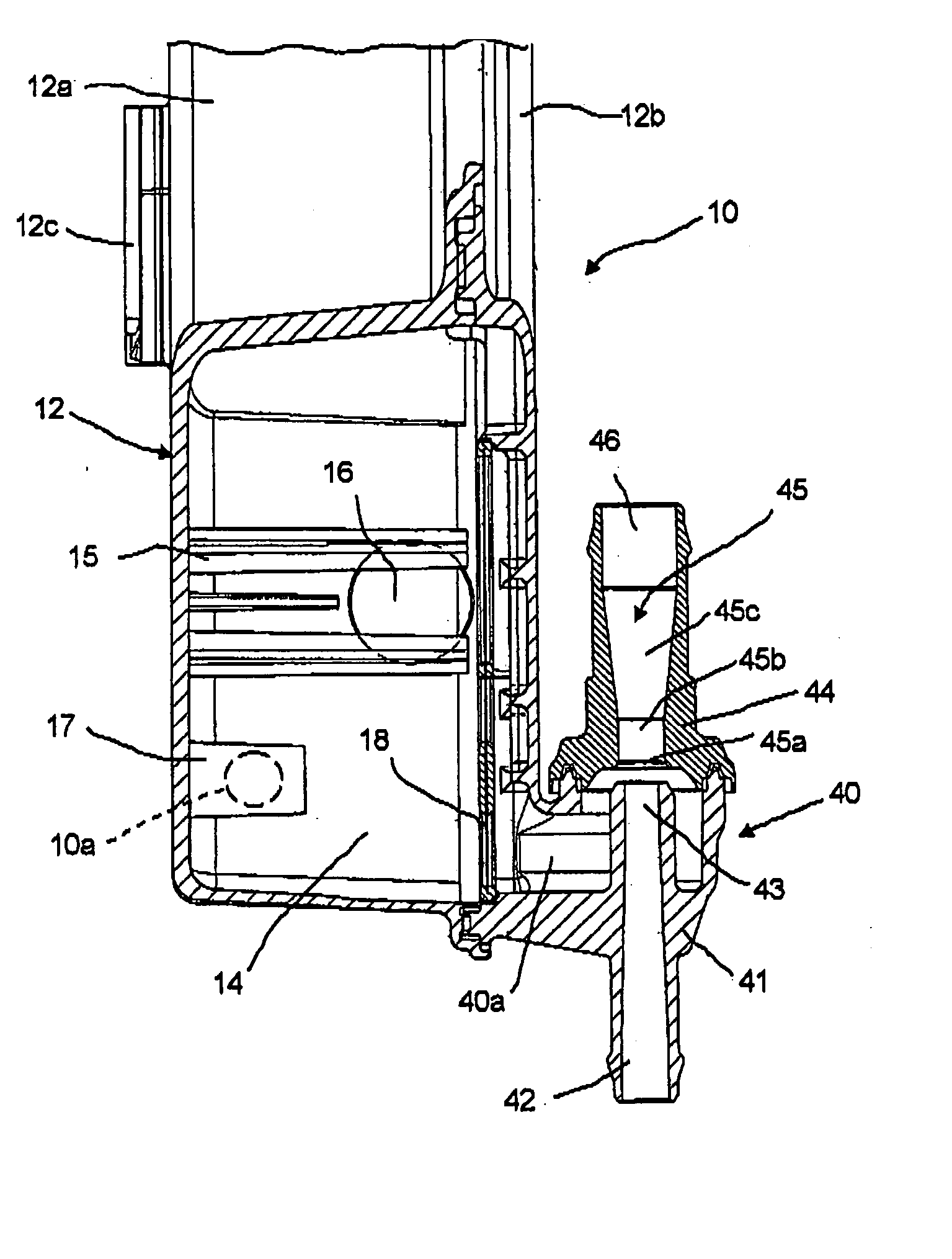
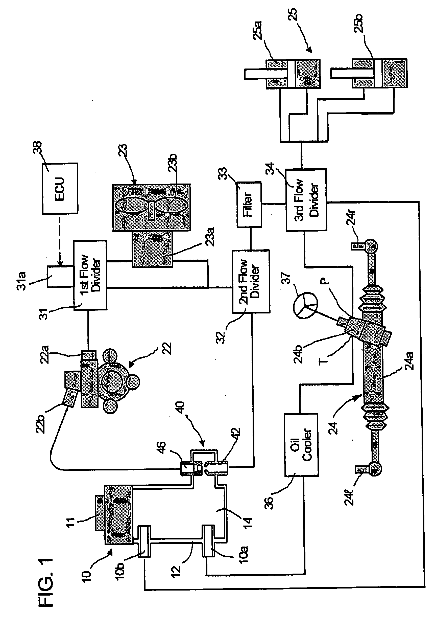
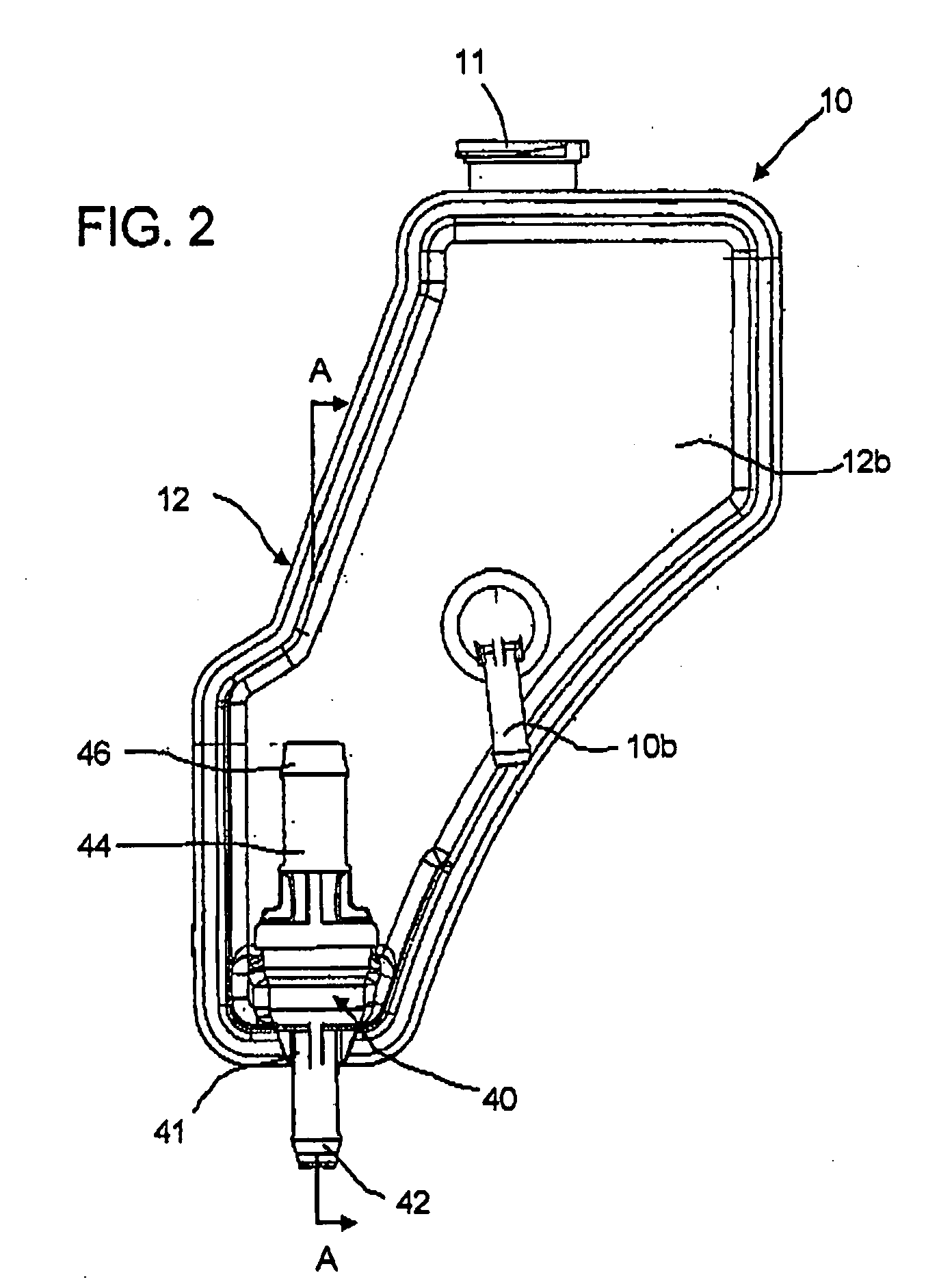
[0026] A hydraulic system for a motor vehicle in a first embodiment according to the present invention will be described hereinafter with reference to FIGS. 1 through 4. The hydraulic system comprises an oil reservoir 10 and an oil pump 22 which constitute an operating oil supply and further comprises a radiator cooling fan device 23, a power steering device 24, and a suspension control mechanism 25 which constitute hydraulically operated function accessories or components for a motor vehicle (not shown).

[0027] The oil pump 22 constituted by, e.g., a vane pump, which is connected to be driven by a crankshaft of a combustion engine (both not shown) of the motor vehicle. The oil pump 22 incorporates a flow control mechanism and a relief valve mechanism (both not shown) therein. The relief valve mechanism operates in an abnormal state to protect the oil pump 22 from damage. The flow control mechanism controls the flow volume discharged from a discharge port 22a to increase in proporti...

second embodiment

[0044] Next, a hydraulic system or circuit device in a second embodiment according to the present invention will be described with reference to FIGS. 5 and 6. Referring now to FIG. 5, a pump suction enhancer 140 is illustrated as being a discrete component separated from the oil reservoir 10. Thus, the oil reservoir 10 is provided with a suction outlet port 19 to open to the lower part of the reservoir chamber 14. As shown in FIG. 6, the pump suction enhancer 140 in the second embodiment includes a body member 147 of a generally block-like shape, which is formed with a through hole 148 and a blind hole 149. The blind hole 149 intersects with the through hole 148 to define an intersection chamber 140a. An inlet section 141 and an outlet section 144 are fixedly screwed respectively into opposite open end portions of the through hole 148, and a reservoir port section 150 is fixedly screwed into an open end portion of the blind hole 149.

[0045] The inlet section 141 is provided with an ...

third embodiment

[0050] A third embodiment of the present invention will be described hereafter with reference to FIGS. 5, 7 and 8. In the third embodiment, another pump suction enhancer 240 shown in FIGS. 7 and 8 is employed in substitution for the pump suction enhancer 140 which is arranged in the hydraulic system shown in FIG. 5. Like the pump suction enhancer 140 in the second embodiment, the pump suction enhancer 240 in the third embodiment is provided as a discrete component which is separated from the oil pump 22 and the oil reservoir 10. As best shown in FIG. 8, the pump suction enhancer 240 is constituted by joining two parts; i.e., an inlet section 241 and an outlet section 244. The inlet section 241 and the outlet section 244 are joined with each other thereby to constitute a body section 247. The pump suction enhancer 240 defines an annular chamber 240a therein to which a reservoir connection port 252 opens, so that the operating oil is drawn from the reservoir 10 to the annular chamber ...


PUM


Abstract

A hydraulic system for a motor vehicle is provided with a pump suction enhancer for boosting the suction of operating oil into a suction port of an oil pump. The pump suction enhancer is composed of a body section for defining a small chamber, a venturi tube passage exposed to the small chamber at an inner end thereof and connected to the suction port of the oil pump, and a nozzle protruding into the small chamber to face the inner end of the venturi tube passage with a space relative to the venturi tube passage in axial alignment with the same for ejecting the operating oil returned from a flow divider into the venturi tube passage thereby to plunge the operating oil from the small chamber into the venturi tube passage. The flow divider divides the operating oil discharged from the oil pump into a return flow to the pump suction enhancer and into a supply flow which passes through a power steering device to return to an oil reservoir. In a first embodiment, the pump suction enhancer is integrally formed with the oil reservoir with the small chamber opening to a reservoir chamber defined in the oil reservoir. In a second embodiment, the pump suction enhancer is provided as a discrete component separated from the oil reservoir, oil pump and the flow divider.

Description

BACKGROUND OF THE INVENTION [0001] 1. Field of the Invention [0002] The present invention relates to a hydraulic system for a motor vehicle incorporating a pump suction enhancer therein for boosting operating oil flow into a suction port of an oil pump, and also relates to an oil reservoir provided bodily with the pump suction enhancer. It further relates to the pump suction enhancer for use in the hydraulic system or in combination with the oil reservoir. [0003] 2. Discussion of the Related Art [0004] In a hydraulic system or circuit device for a motor vehicle, the oil flow discharged from a power steering oil pump tends to become larger with increase in number of function components or accessories such as a radiator cooling fan device, suspension control actuators and the like in addition to a power steering device. With the large discharge flow from the oil pump, it has been required to improve the suction of a large return oil flow into the oil pump in order to prevent cavitatio...

Claims


Application Information

Patent Timeline
IPC IPC(8): F04B35/00F04B17/00F15B1/26
CPCB62D5/062B62D5/075F15B21/047F15B1/265F15B1/26
Inventor SMITH, STEVE CARLTONKIMOTO, MASAMIIMANISHI, TAKASHIKABEYA, TERUAKI
Owner JTEKT CORP
Why Eureka
Try Eureka