Lithographic projection apparatus and a device manufacturing method using such lithographic projection apparatus

a technology of lithographic projection and manufacturing method, which is applied in the direction of printers, instruments, photographic processes, etc., can solve the problems of aberration and hypothetical vertical lines that are not compensated, and achieve the effect of optimal image quality

Active Publication Date: 2006-01-12
ASML NETHERLANDS BV
View PDF12 Cites 74 Cited by
  • Summary
  • Abstract
  • Description
  • Claims
  • Application Information

AI Technical Summary

Benefits of technology

[0027] It is an object of the present invention to effect adjustments to the projection system of lithographic projection apparatus to compensate for the effect of lens aberrations in such a manner as to provide optimal image quality for a particular application, that is for a particular combination of mask (for example the product pattern) and illumination mode.
[0042] In one embodiment, the control system incorporates a realignment controller for re-measuring at least one aberration value when the predicted effect on one or more image parameters with time is greater than a corresponding (e.g. user-defined) threshold value. The use of thresholds for the lithographic parameters means that appropriate realignments are made only when these thresholds are exceeded, so that the effect on throughput is minimised whilst still keeping good imaging performance.

Problems solved by technology

The fact that, in this example, the effect of the aberrations so far as hypothetical vertical lines are concerned is not compensated for optimally is immaterial since no such vertical lines require to be defined accurately in the product or the relevant part of the product.

Method used


Image

  • Lithographic projection apparatus and a device manufacturing method using such lithographic projection apparatus
  • Lithographic projection apparatus and a device manufacturing method using such lithographic projection apparatus
  • Lithographic projection apparatus and a device manufacturing method using such lithographic projection apparatus

Examples


Embodiment Construction

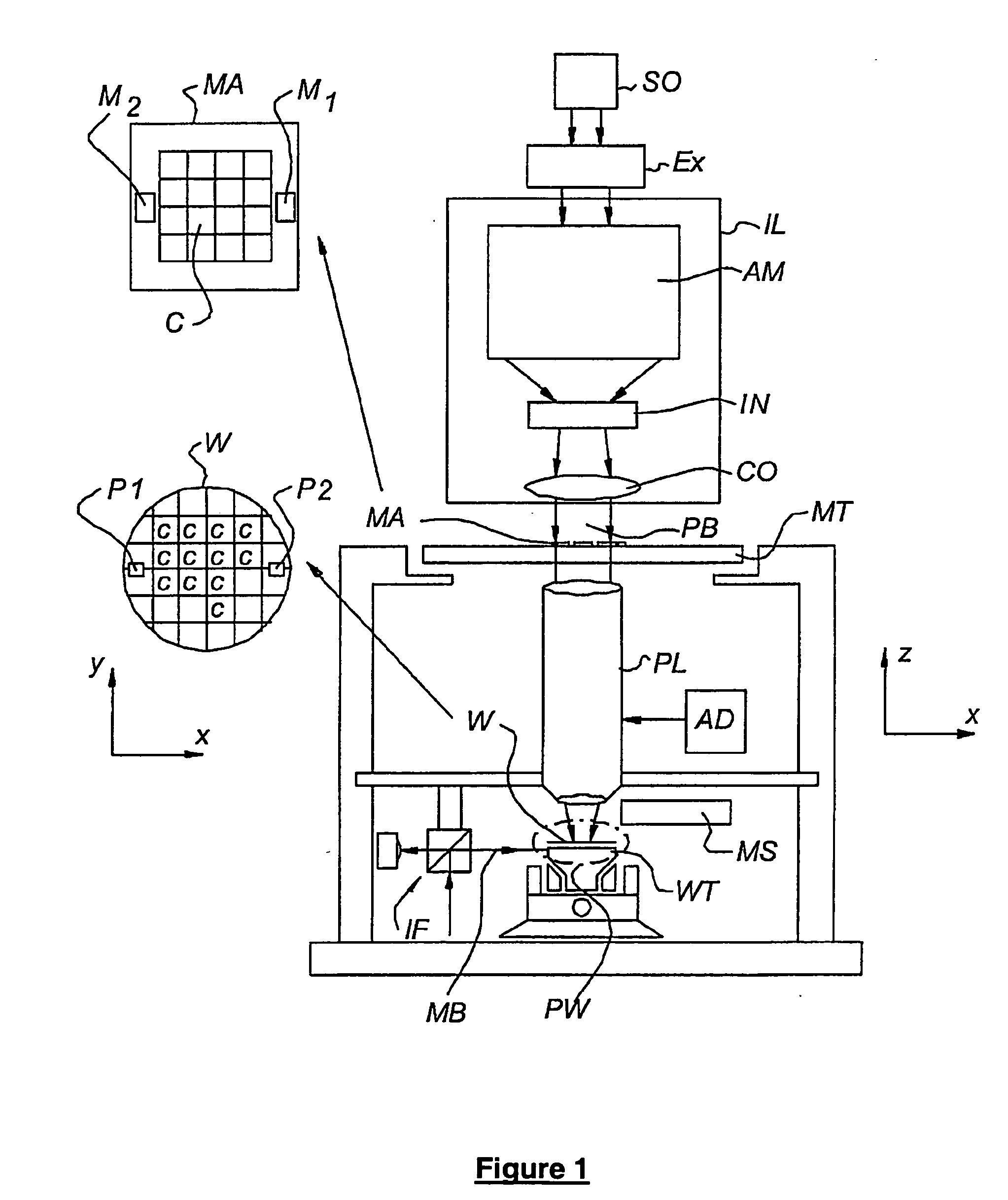
[0051]FIG. 1 schematically depicts lithographic projection apparatus comprising at least one marker structure in accordance with an embodiment of the invention. The apparatus comprises:

[0052] an illumination system IL for providing a projection beam PB of radiation (e.g. UV or EUV radiation). In this particular case, the radiation system also comprises a radiation source SO;

[0053] a first support structure MT (e.g. a mask table) for supporting a patterning device, MA (e.g. a mask) and connected to first positioner (not shown) for accurately positioning the patterning device with respect to item PL;

[0054] a second support structure WT (e.g. a wafer table) for holding a substrate, W (e.g. a resist-coated silicon wafer) and connected to second positioner PW for accurately positioning the substrate with respect to item PL; and

[0055] a projection system PL (e.g. a reflective projection lens) for imaging a pattern imported to the projection beam PB by patterning device MA onto a targe...


PUM

PropertyMeasurementUnit
wavelengthaaaaaaaaaa

Abstract

A manufacturing method is utilized in lithographic projection apparatus in order to enable all aberrations to be compensated for but with those aberrations that are of most significance to the particular application (the particular pattern, illumination mode, etc.) being given precedence over aberrations that are of lesser significance in relation to that particular application. The method uses a substrate having a target portion for receiving an image, a mask for applying a pattern in accordance with a required patterning application, and a projection system to project a selected beam of radiation onto the mask to produce a specific required patterned beam providing an image of the pattern on the target portion. In order to compensate for the aberrations in a manner that gives precedence to those aberrations of particular significance to the required application, the method incorporates the steps of predicting projection system aberration changes with time, determining the application-specific effect on certain parameters of the image of such predicted projection system aberration changes with respect to certain measured aberration values, generating a control signal specific to the required patterned beam according to such predicted projection system aberration changes in the projection system aberrations with time and their application-specific effect on certain parameters of the image; and carrying out imaging adjustments in dependence on the control signal to compensate for the application-specific effect of the predicted changes in the aberrations on the image. The adjustments are therefore determined optimally for the given application.

Description

FIELD OF THE INVENTION [0001] This invention relates to lithographic projection apparatus and a device manufacturing method using such lithographic projection apparatus. BACKGROUND OF THE INVENTION [0002] The invention finds application, for example, in the field of lithographic projection apparatus incorporating a radiation system for supplying a projection beam of radiation, a support structure for supporting a patterning device, which serves to pattern the projection beam according to a desired pattern, a substrate table for holding a substrate; and a projection system for projecting the patterned beam onto a target portion of the substrate. [0003] The term “patterning device” as employed here should be broadly interpreted as referring to devices and structures that can be used to endow an incoming radiation beam with a patterned cross-section, corresponding to a pattern that is to be created in a target portion of the substrate; the term “light valve” can also be used in this co...

Claims


Application Information

Patent Timeline
Patent Type & Authority Applications(United States)
IPC IPC(8): G03C5/00G03B27/00G06F17/50G03F9/00
CPCG03F7/70258G03F7/70491G03F7/70891G03F7/706G03F7/705G03F9/7046G03F7/20
Inventor JEUNINK, ANDRE BERNARDUSAKHSSAY, M'HAMEDBASELMANS, JOHANNES JACOBUS MATHEUSCOMMISSARIS, FRANCISCUS ANTONIUS CHRYSOGONUS MARIEDE GROOT, SIMONTEL, WIM TJIBBOVAN DER HOFF, ALEXANDER HENDRIKUS MARTINUSVAN DE STADT, ARNOUTVAN DIJK, REMCO MARCEL
Owner ASML NETHERLANDS BV
Why Eureka
Try Eureka