Screening apparatus for water treatment with membranes

a technology of water treatment and screening apparatus, applied in the field of screening, can solve the problems of affecting the effect of pre-screening feed stream, and affecting the effect of screening backwashing

Inactive Publication Date: 2006-01-12
ZENON ENVIRONMENTAL INC
View PDF29 Cites 44 Cited by
  • Summary
  • Abstract
  • Description
  • Claims
  • Application Information

AI Technical Summary

Benefits of technology

[0024] The upstream aerator may provide air scouring of the screening surface during forward operation or cause a backwash of the screening surface during a cleaning or deconcentration procedure. The screening apparatus may further have an overflow weir or drain upstream of the screening surface for removing solids retained by the screen, for example during deconcentration or cleaning procedures. Solids retained by the screen in an upstream area may be sent to a waste stream or re-cycle to other parts of the system. Some of these elements may be combined. For example, an aerator may simultaneously scour the screening surface with bubbles, float screenings in the upstream area to an overflow to assist in their removal or recycle, and cause a backwash of the screen.

Problems solved by technology

The membrane fibers or sheets can be damaged by trash, roped hair and other fibrous materials that may become entangled with or around the membrane fiber or sheet.
Moreover, trash, hair and other fibrous materials are difficult to remove from membranes because the membrane fibers or sheets are arranged relatively close to one another and cannot withstand repeated vigorous mechanical cleaning.
However, pre-screening the feed stream is typically only effective in reducing the concentrations of trash and other fibrous materials that are roped or balled together in the feed.
Pre-screening the raw sewage stream does not adequately remove individual strands or small bundles of trash and fibrous materials that can later come together to form relatively thick roped lengths or balled bundles inside the waste water treatment system.
Once inside the water treatment system the individual hairs are prone to roping and balling together.
The roped hairs become entangled with the membrane fibers causing wear and damage.
Additionally, recontamination of the pre-screened water is common since the water may pass through open tanks included in many water treatment facilities.
Debris such as leaves from nearby trees or other contaminates brought by the wind frequently blows into the tanks.
Further, the mechanical design of screens themselves may make them expensive or difficult to install or operate, particularly at high flows and fine mesh sizes.

Method used


Image

  • Screening apparatus for water treatment with membranes
  • Screening apparatus for water treatment with membranes
  • Screening apparatus for water treatment with membranes

Examples


Embodiment Construction

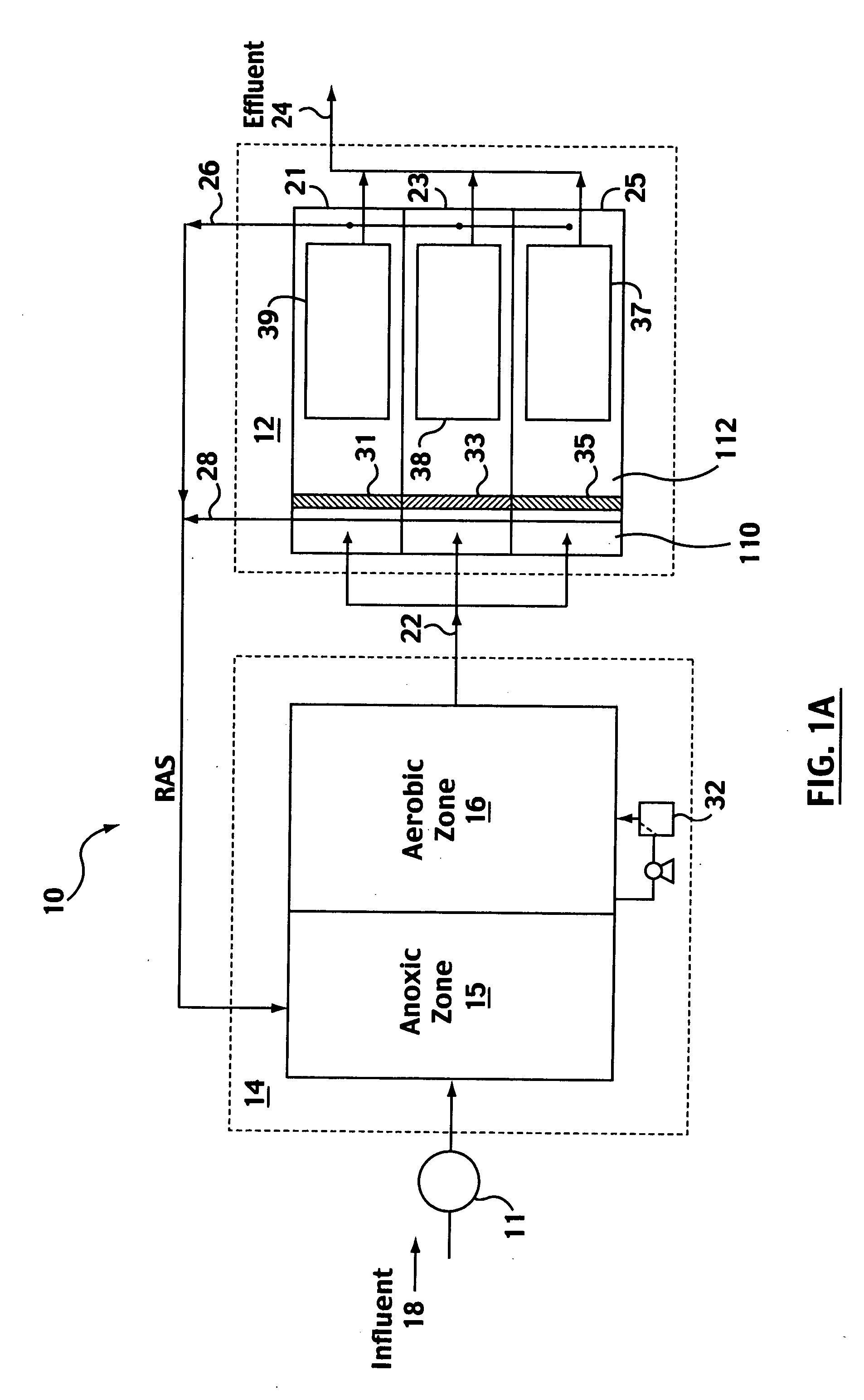
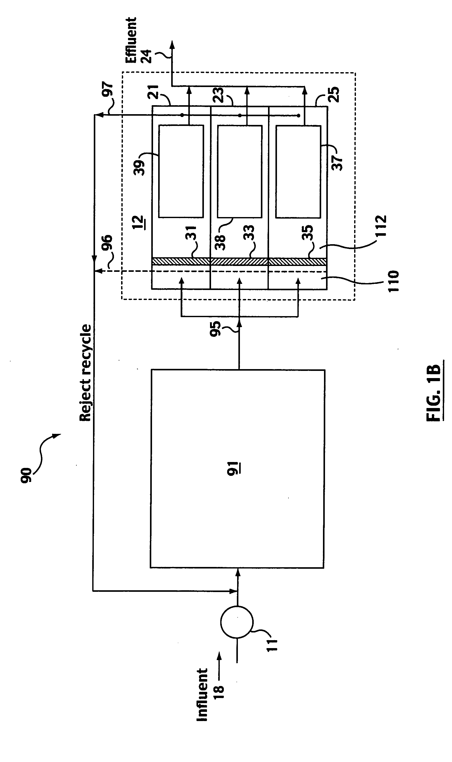
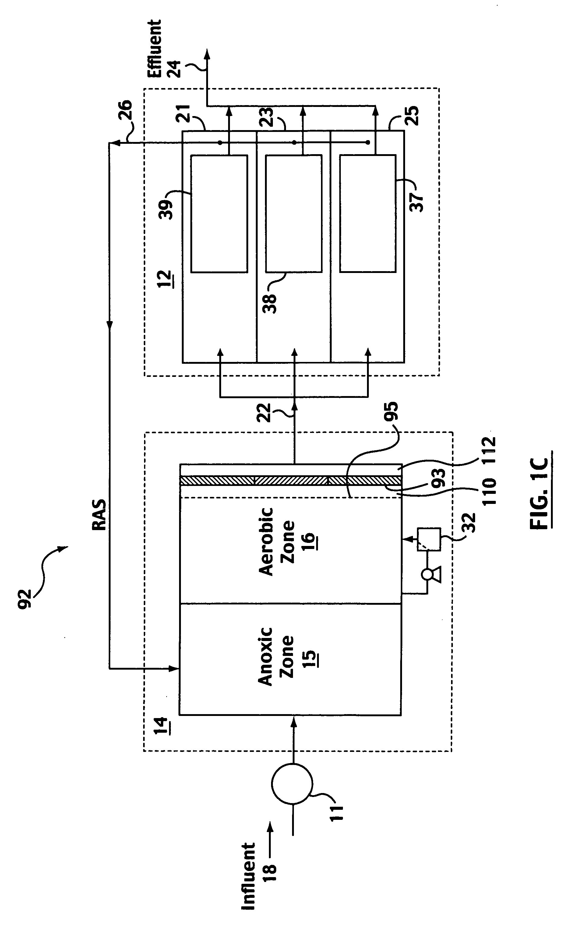
[0043]FIG. 9 shows a screening apparatus 100 having a static screen 35 mounted in a vessel 102. The vessel 102 may be, for example, a tank, trough, channel or other conduit or holding means for water. The vessel 102 has a bottom 104 and a pair of opposed sides 106, the closer of the two opposed sides 106 not shown, defining a pathway for water to flow through the vessel 102 by generally open channel flow. The sides 106 may be curved, as in a round tank. The static screen 35 spans between the opposed sides 106 either directly or by spanning between partitions or other non-porous elements attached to the sides 106. The static screen 35 also extends from the bottom 104 of the vessel to above a surface level 108 of the water in the vessel 102, either directly or by extending between non-porous elements attached to the bottom 104 or across a higher elevation of the vessel 102. In particular, the static screen 35 may have a screening surface 35a and a non-porous surface 35b. Water passing...


PUM

PropertyMeasurementUnit
sizeaaaaaaaaaa
sizeaaaaaaaaaa
surface areaaaaaaaaaaa

Abstract

A static screen used upstream of a membrane assembly within a water treatment system has a screening surface with a number of openings distributed over its area. Liquid flows through the screening surface to reach the membrane assembly. Various shapes of screening surfaces are described including undulating panels and geometric shapes. Methods for cleaning the screen are described including aeration and backwashing. Various treatment systems or process designs incorporating the screen are described.

Description

[0001] This is an application claiming the benefit under 35 USC 119(e) of U.S. Application Ser. Nos. 60 / 584,168, filed Jul. 1, 2004; 60 / 585,579, filed Jul. 7, 2004; 60 / 585,580, filed Jul. 7, 2004; 60 / 612,515, filed Sep. 24, 2004; and, 60 / 618,980, filed Oct. 18, 2004. U.S. Application Ser. Nos. 60 / 584,168; 60 / 585,579; 60 / 585,580; 60 / 612,515; and, 60 / 618,980 are incorporated herein, in their entirety, by this reference to them. Canadian Application Serial No. 2,497,391 filed Feb. 17, 2005 by Zenon Environmental Inc. is incorporated herein, in its entirety by this reference to it.FIELD OF THE INVENTION [0002] This invention relates to screens, to a process of operating or cleaning a screen and to a water treatment apparatus or process using screens, for example a water treatment apparatus or process using membranes. BACKGROUND OF THE INVENTION [0003] The following description of the background of the invention is not an admission that anything discussed in the description is citable as...

Claims


Application Information

Patent Timeline
Patent Type & Authority Applications(United States)
IPC IPC(8): C12Q1/04B01D35/00
CPCB01D35/027B01D61/147B01D61/18B01D65/08B01D2311/04B01D2315/06B01D2321/04B01D2321/185C02F1/001C02F1/40C02F1/444C02F3/1273C02F2303/24B01D61/16B01D61/145B01D2311/16Y02W10/10
Inventor COTE, PIERRE LUCIENTHOMPSON, DOUG JOSEPHPAWLOSKI, JENNIFER LYNNLIU, MINGGANG
Owner ZENON ENVIRONMENTAL INC
Why Eureka
Try Eureka