Installation for filling a mould with liquid metal and process employing this installation

a technology of liquid metal and installation, which is applied in the direction of molten metal pouring equipment, casting parameters measurement/indication devices, moulding machine components, etc., can solve the problem of lack of knowledge of the real level

Inactive Publication Date: 2006-01-19
SOC DETUD & DE REALISATIONS TECHN S E R T
View PDF2 Cites 14 Cited by
  • Summary
  • Abstract
  • Description
  • Claims
  • Application Information

AI Technical Summary

Benefits of technology

[0027] a predetermined threshold of the impression is chosen, the instant is detected at which the level of liquid metal reaches this threshold, a latent period is allowed to lapse, depending in particular on the instantaneous value of the flowrate of molten metal poured from the vessel, and the admission of liquid metal in the mould is stopped at the end of this latent period.

Problems solved by technology

However, this known solution presents a drawback, connected in particular with its lack of knowledge of the real level of filling of the mould in the course of the casting process.

Method used


Image

  • Installation for filling a mould with liquid metal and process employing this installation
  • Installation for filling a mould with liquid metal and process employing this installation
  • Installation for filling a mould with liquid metal and process employing this installation

Examples


Embodiment Construction

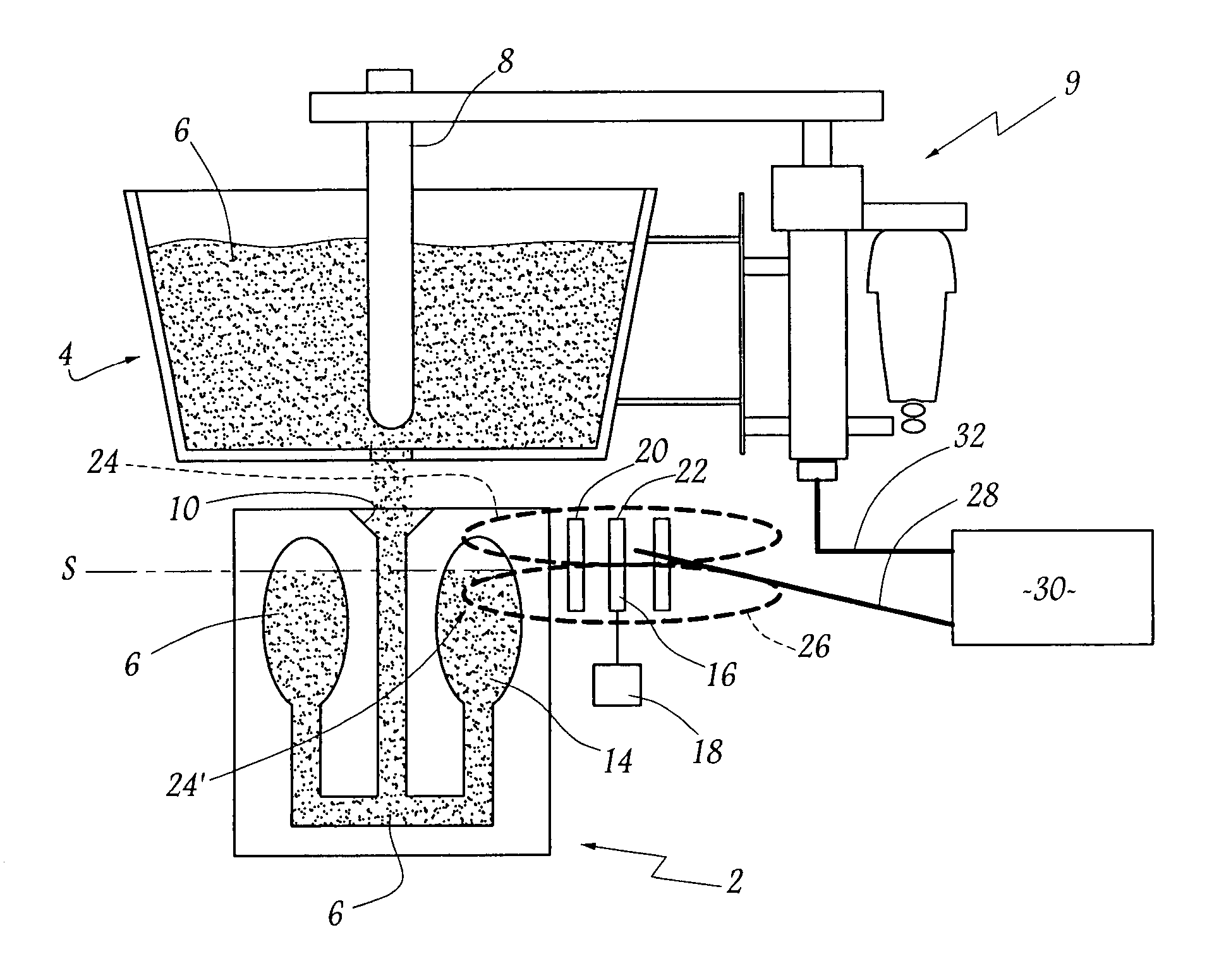
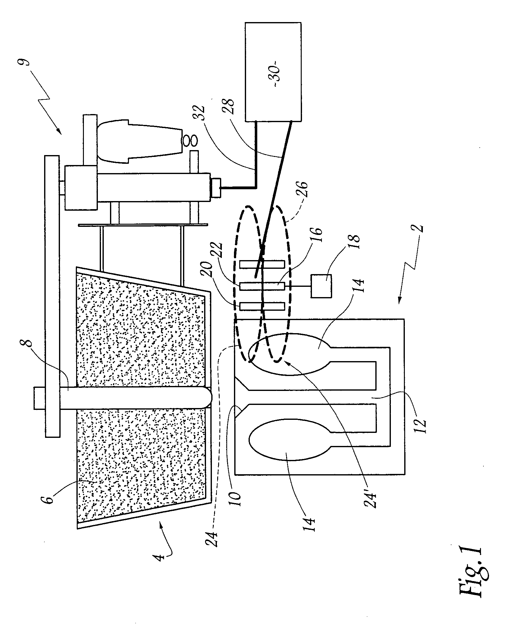
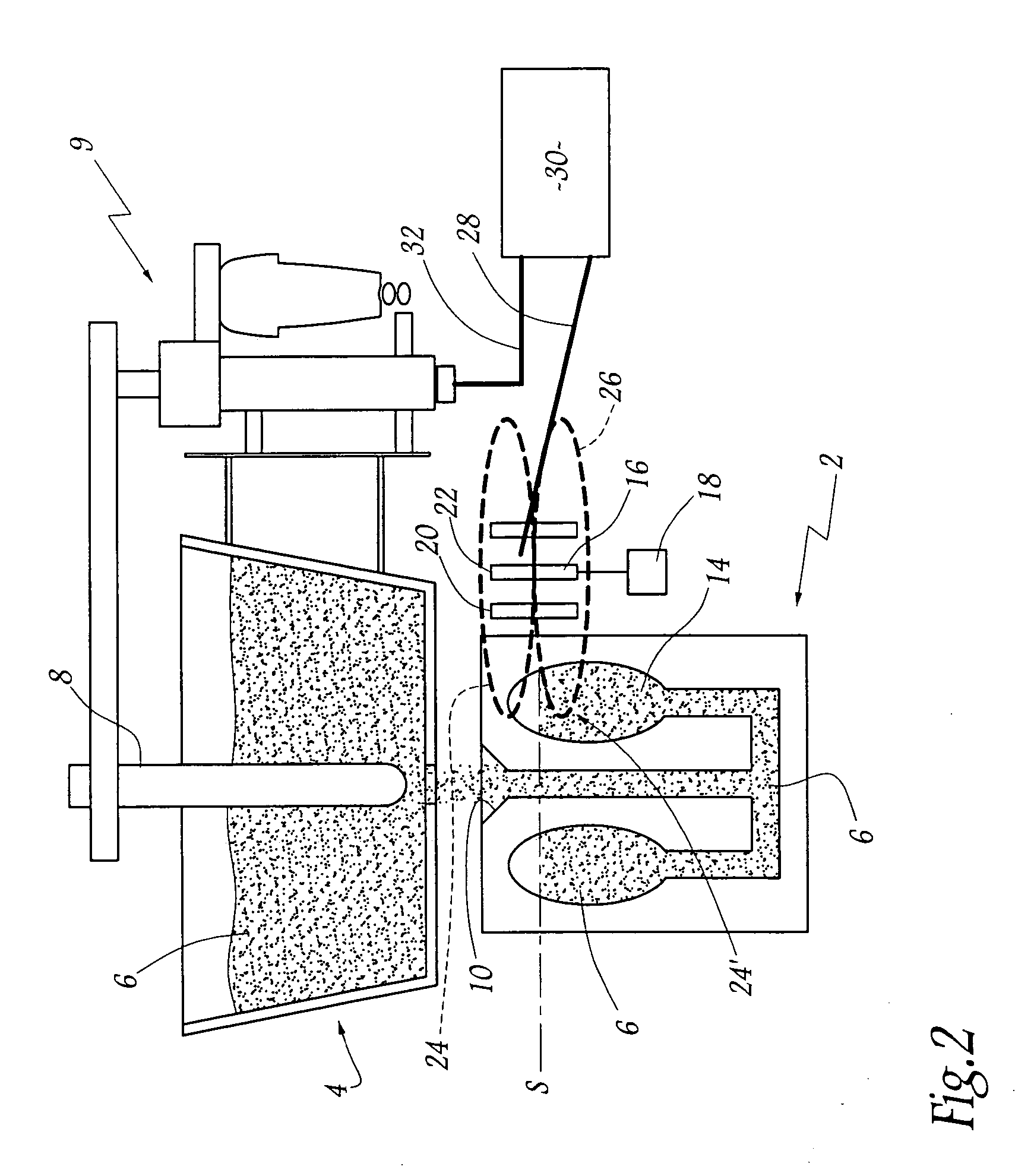
[0032] Referring now to the drawings, the installation of FIGS. 1 and 2 comprises different moulds, of which only one has been shown, given reference 2. In service, this mould circulates beneath a vessel 4 which is filled with a liquid molten metal 6 which is for example cast-iron or steel. This metal was poured in the vessel 4 in conventional manner via a ladle (not shown).

[0033] The bottom of the vessel 4 is closed, in known manner, by a stopper 8, also called stopple. The latter may be manoeuvred along its principal axis, namely vertically in FIG. 1, via an actuator 9 of conventional type.

[0034] Each mould, which is of globally parallelepipedic shape, conventionally comprises a casting bowl 10, of truncated shape, into which flows the molten metal 6 poured from the vessel 4. This bowl 10 extends in a feed channel 12 which opens out into at least one impression 14. In the example described and shown, two such impressions 14 are provided, which have been illustrated schematically...


PUM

PropertyMeasurementUnit
depthaaaaaaaaaa
depthaaaaaaaaaa
depthaaaaaaaaaa

Abstract

The installation according to the invention comprises at least one mould, a vessel intended to receive the liquid metal and means for directly determining the evolution of the level of molten metal in the impression of the mould. These determination means comprise means for detecting the presence of this liquid metal in the impression, particularly of electromagnetic nature, which are adapted to penetrate at least partially in the interior volume of this impression.

Description

FIELD OF THE INVENTION [0001] The present invention relates to an installation for filling a mould with liquid metal, as well as to a process allowing this installation to be employed. BACKGROUND OF THE INVENTION [0002] In the technical domain of foundrywork, it is known to employ a succession of moulds, also called boxless moulds, which are made of sand. Each mould conventionally comprises a casting bowl intended to receive the molten metal, as well as at least one impression connected to this bowl via a feed channel. In service, it is question of displacing each mould in the direction of a casting machine adapted to pour molten metal. [0003] This casting operation is subjected to several requirements. [0004] Firstly, it is important to flood the casting bowl rapidly and to maintain it in the full state while the metal is propagating in the direction of the impressions. In effect, this ensures high-quality casting, bereft of voids, defects and trapped gas. [0005] It is also necessa...

Claims


Application Information

Patent Timeline
Patent Type & Authority Applications(United States)
IPC IPC(8): B22D37/00B22D2/00
CPCB22D37/00B22D2/003
Inventor DUSSUD, MICHELROBIN, ALAIN
Owner SOC DETUD & DE REALISATIONS TECHN S E R T
Why Eureka
Try Eureka