Heat pipe heat sink with holeless fin module

a heat sink and heat sink technology, applied in the direction of lighting and heating apparatus, basic electric elements, semiconductor devices, etc., can solve the problems of ineffective installation of more cooling fans, poor performance, poor heat dissipation effect, etc., and achieve the effect of enhancing the state of the art and efficient dissipation of hea

Inactive Publication Date: 2006-01-19
WAFFER TECH +1
View PDF8 Cites 56 Cited by
  • Summary
  • Abstract
  • Description
  • Claims
  • Application Information

AI Technical Summary

Benefits of technology

[0009] The heat pipe heat sink provided by the present invention has a holeless heat dissipating fin module which is not only much more convenient for manufacturing a heat pipe heat sink, but also capable of quickly transferring the heat generated by an electrical component into the heat pipe and uniformly distributing the heat to each of the heat dissipating fins.
[0011] The top of the heat conducting plate is attached to the bottom surface of the heat conducting member, while the bottom of the heat conducting plate is thermally connected to the top surface of an electrical component. Via the heat conducting plate, a uniform heat connection end surface is formed below the heat conducting member. The heat transferred into the heat conducting plate has dual routes for simultaneous transfer; heat can be transferred to the heat dissipating fin module via either the heat conducting member or the heat pipe. The heat transferred is equally distributed among the heat dissipating fins of the heat dissipating fin module for quick dissipation into the surrounding air. The present invention more efficiently dissipates heat than the conventional art. The present invention, therefore, enhances the state of the art.

Problems solved by technology

If a system only uses cooling fans to dissipate heat, it may have poor performance though.
It may have poor performance because the air brought in from the outside may not always be much cooler than the air in the system's interior; in the summer the exterior temperature could reach 35 degree C. or more.
Therefore, installing more cooling fans is in vain.
Moreover, within a system's housing there is not much extra space that could be used for the installation of extra fans.
Such a method is likely to damage or distort the heat dissipation fin module though.
It is because of this damage or distortion, which occurs during assembly, that the tight fit between the heat pipe and the fin module is not optimal.
However, remedying the gaps caused by the forcible insertion through the injection of hot solder does not greatly enhance performance.
Further, the application of the injection remedy is difficult.
However, because the heat conducting column is forcibly inserted into the bored holes, the distortion problem of the heat dissipating plates still exists.
The soldering problem also still exists when the distortion problem of the heat dissipating plates is remedied; the hot solder still flows down and concentrates at the lower semi-circle of the circular wall.
However, this structure requires the insertion and soldering of the third metal material.
Because of this, many gaps still remain between the bored holes and the heat pipe.

Method used


Image

  • Heat pipe heat sink with holeless fin module
  • Heat pipe heat sink with holeless fin module
  • Heat pipe heat sink with holeless fin module

Examples


Embodiment Construction

[0023] Reference will now be made in detail to the preferred embodiments of the present invention, examples of which are illustrated in the accompanying drawings. Wherever possible, the same reference numbers are used in the drawings and the description to refer to the same or like parts.

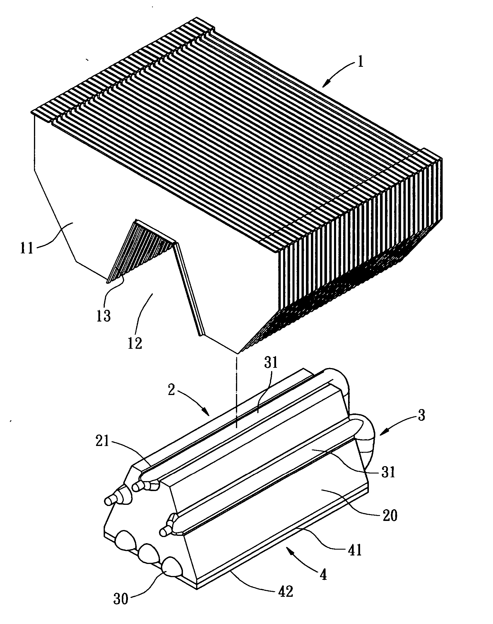
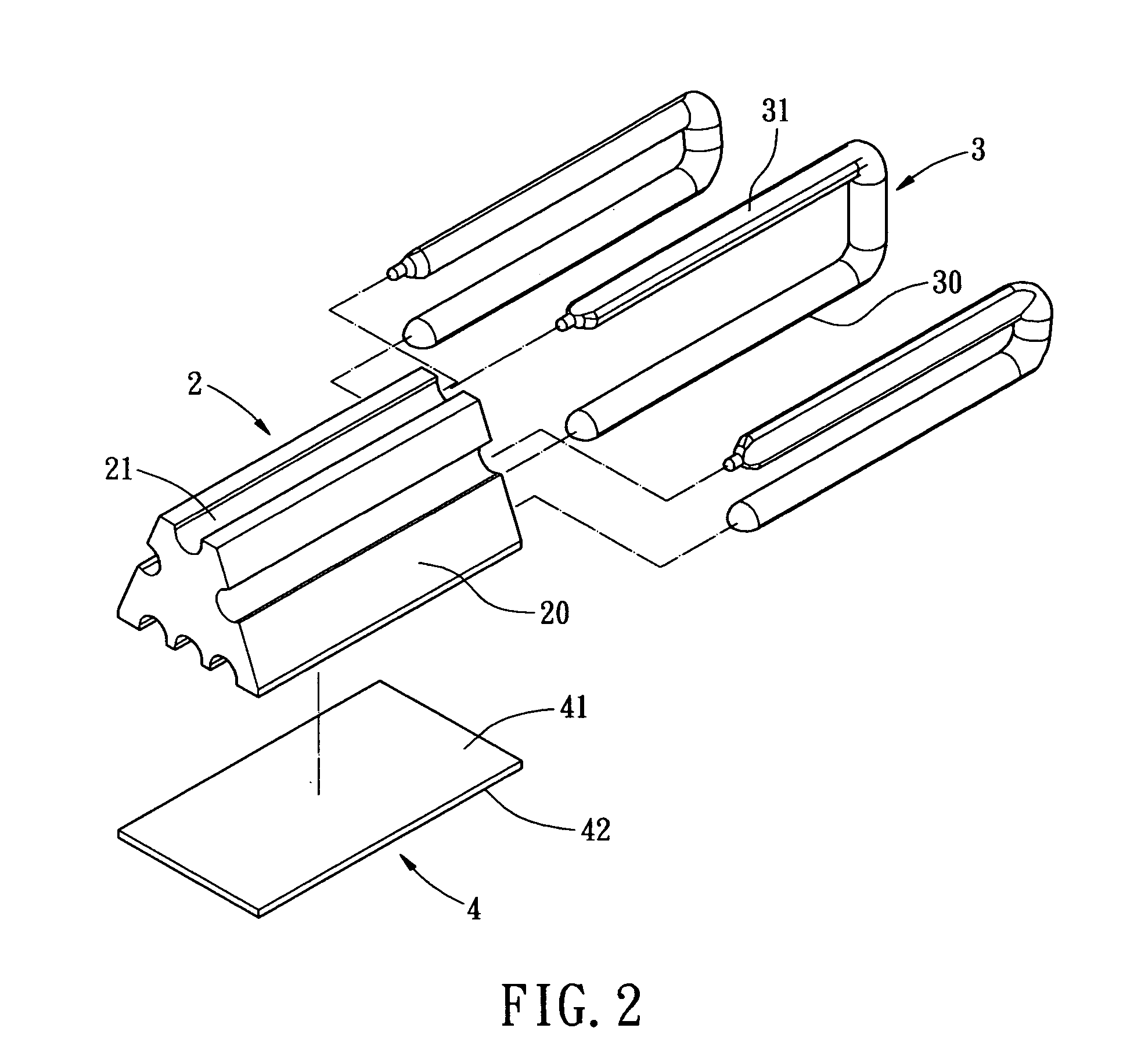
[0024] Referring to FIGS. 2 through 5, one preferred embodiment of a heat pipe heat sink of the present invention is shown. The heat pipe heat sink includes a heat dissipating fin module 1; a heat conducting member 2 which is combined with the heat dissipating fin module 1; one or more heat pipes installed on the heat conducting member2, which is thermally connected to the heat dissipating fin module 1; and a heat conducting plate 4 which is thermally connected to the end surface of the heat conducting member 2.

[0025] The heat dissipating fin module 1, as illustrated in FIG. 3, is assembled by stacking a plurality of independent heat dissipating fins 11. The heat dissipating fin module 1 has a con...


PUM


Abstract

A heat pipe heat sink with a holeless fin module is disclosed in the present invention. Because of the holeless arrangement the heat pipe heat sink is much more convenient for manufacturing. The heat generated by an electrical component can quickly be transferred into the heat pipe and uniformly distributed to each of the heat dissipating fins. The heat pipe heat sink includes a heat dissipating fin module, a heat conducting member, one or more heat pipes installed on the heat conducting member, and a heat conducting plate which is thermally connected to the heat conducting member and the electrical component. The end surface of the heat conducting member with the heat pipe installed thereon is convenient for application of an adhesive because the end surface and the pipe wall of the heat pipe are exposed outside of the heat dissipating fin module before any combination takes place. The top of the heat conducting plate is attached to the bottom surface of the heat conducting member, while the bottom of the heat conducting plate is thermally connected to the top surface of an electrical component. Via the heat conducting plate, a uniform heat connection end surface is formed below the heat conducting member.

Description

BACKGROUND OF THE INVENTION [0001] The present invention relates in general to a heat pipe heat sink, and more particularly, to a heat pipe heat sink with a holeless fin module. Because of the holeless arrangement the present invention is much more convenient for manufacturing a heat pipe heat sink. The heat generated by an electrical component can quickly be transferred into the heat pipe and uniformly distributed to each of the heat dissipating fins. [0002] Currently, the most common heat dissipation device is a cooling fan which is fixed onto the housing of some piece of electrical equipment. This cooling fan facilitates air circulation by replacing the inner heated air with the cooler outer air. If a system only uses cooling fans to dissipate heat, it may have poor performance though. It may have poor performance because the air brought in from the outside may not always be much cooler than the air in the system's interior; in the summer the exterior temperature could reach 35 d...

Claims


Application Information

Patent Timeline
Patent Type & Authority Applications(United States)
IPC IPC(8): F28D15/00
CPCF28D15/0233H01L23/3672H01L23/427H01L23/467H01L2924/0002F28D15/0275H01L2924/00
Inventor WANG, JACKLIN, MICHAELMA, CHARLESLIN, L.H.
Owner WAFFER TECH
Why Eureka
Try Eureka