Wear part for a crusher

a technology of wear parts and distributor plates, applied in the field of distributor plates, can solve the problems of wear at the periphery of distributor plates, and achieve the effect of reducing the down time and prolonging the li

Active Publication Date: 2006-01-19
SANDVIK INTELLECTUAL PROPERTY AB
View PDF10 Cites 38 Cited by
  • Summary
  • Abstract
  • Description
  • Claims
  • Application Information

AI Technical Summary

Benefits of technology

[0010] It is an object of the present invention to provide a distributor plate which ha

Problems solved by technology

A possible explanation is that much of the wear at the periphery of the distribu

Method used


Image

  • Wear part for a crusher
  • Wear part for a crusher
  • Wear part for a crusher

Examples


Embodiment Construction

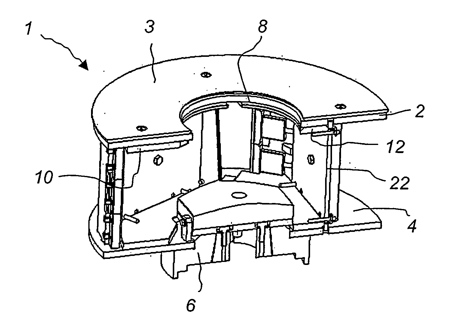
[0036]FIG. 1 shows a rotor 1 for use in a VSI-crusher. The rotor 1 has a roof in the form of an upper disc 2 having a top wear plate 3 and a floor in the form of a lower disc 4. The lower disc 4 has a hub 6, which is welded to the disc 4. The hub 6 is to be connected to a shaft (not shown) for rotating the rotor 1 inside the housing of a VSI-crusher.

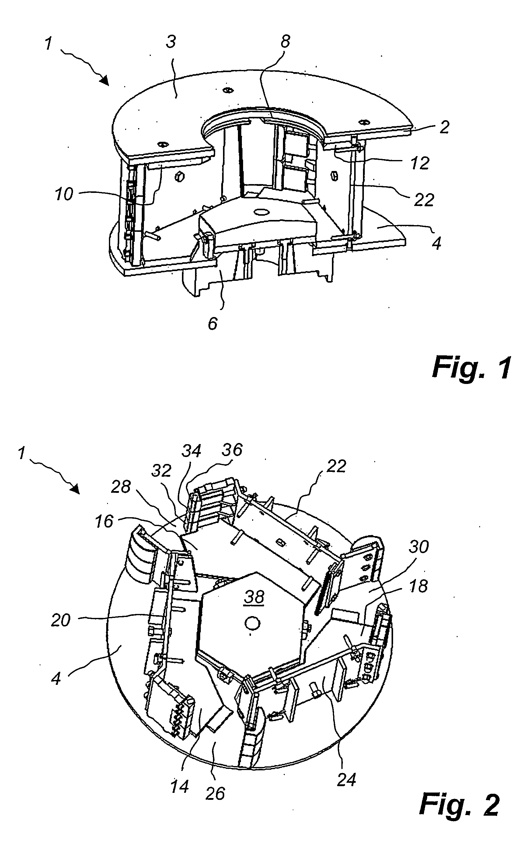
[0037] The upper disc 2 has a central opening 8 through which material to be crushed can be fed into the rotor 1. The upper disc 2 is protected from wear by upper wear plates 10 and 12. The upper disc 2 is protected from rocks impacting the rotor 1 from above by the top wear plate 3. As is better shown in FIG. 2 the lower disc 4 is protected from wear by three lower wear plates 14, 16 and 18.

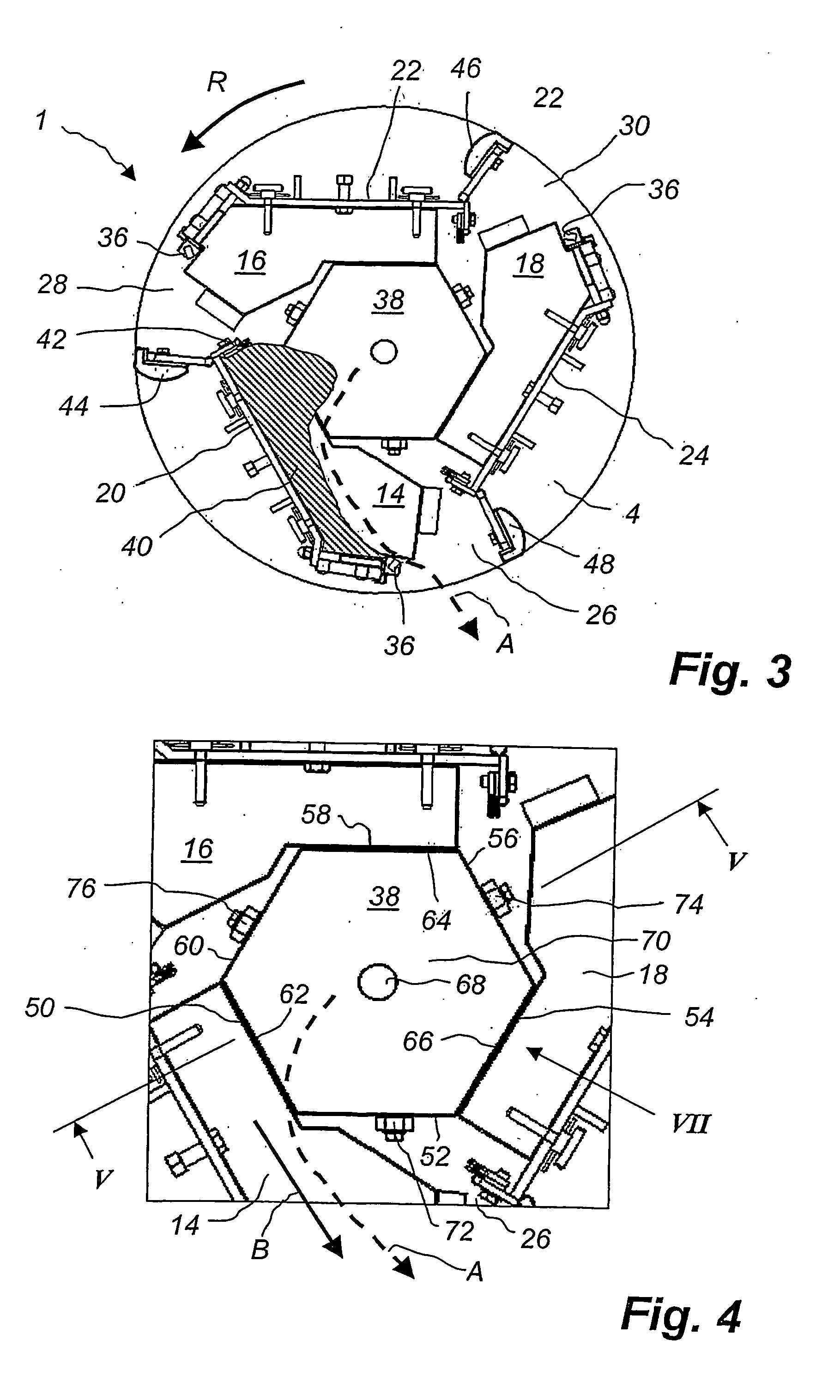
[0038] The upper and lower discs 2, 4 are separated by and held together by a vertical rotor wall which is separated into three wall segments 20, 22 and 24. The gaps between the wall segments 20, 22, 24 define outflow openings 26, 28, 30 through wh...


PUM


Abstract

A distributor plate adapted to be releasably mounted on a horizontal lower disc of a rotor of a vertical shaft impact crusher. The rotor has an opening for the intake of material to be crushed and at least one outflow opening for material leaving the rotor. The distributor plate is an equilateral polygon as seen from above.

Description

TECHNICAL FIELD OF THE INVENTION [0001] The present invention relates to a distributor plate adapted to be releasably mounted on a horizontal lower disc of a rotor of a vertical shaft impact crusher, said rotor having an opening for the intake of material to be crushed and at least one outflow opening for material leaving the rotor. [0002] The present invention also relates to a rotor for a vertical shaft impact crusher, the rotor having an opening for the intake of material to be crushed, at least one outflow opening for material leaving the rotor, and at least one lower wear plate and a distributor plate releasably mounted on a horizontal lower disc of the rotor. BACKGROUND ART [0003] Vertical shaft impact crushers (VSI-crushers) are used in many applications for crushing hard material like rocks, ore etc. U.S. Pat. No. 3,154,259 describes a VSI-crusher comprising a housing and a horizontal rotor located inside the housing. Material that is to be crushed is fed into the rotor via ...

Claims


Application Information

Patent Timeline
IPC IPC(8): B02C19/00B02C13/18
CPCB02C2013/28681B02C13/1835
Inventor DALLIMORE, ROWANFENSOME, GEORGELOVEN, BJORNNORMAN, SVEN-HENRIK
Owner SANDVIK INTELLECTUAL PROPERTY AB
Why Eureka
Try Eureka