Method and apparatus for molding a laminated trim component without use of slip frame

Active Publication Date: 2006-01-19
HERBERT OLBRICH
View PDF18 Cites 15 Cited by
  • Summary
  • Abstract
  • Description
  • Claims
  • Application Information

AI Technical Summary

Benefits of technology

[0010] In view of the above, it is an object of the present invention to provide a method and an apparatus for molding a sheet-form material to produce a molded product, while avoiding the use of a separate or external slip frame. It is a further particular object of the invention to minimize the amount of material waste at an edge or edges of the molded product. Ano

Problems solved by technology

The conventionally known apparatuses as described above suffer several disadvantages arising directly due to the use of the slip frame.
Most importantly, the use of a slip frame necessarily requires the provision of a rather large surplus edge rim of the raw material protruding laterally beyond the edge of the mold.
However, the edge rim waste becomes gravely significant in connection with relatively small products or products that are relatively narrow but long.
This is conventionally unavoidable because the conventional slip frame is spaced laterally by at least about 10 mm away from the outer edges of the mold, the slip frame itself typically has a width of at least about 25 mm, and a surplus rim edge protruding at least about 15 mm outwardly from the slip frame is typically left to allow for the slip

Method used


Image

  • Method and apparatus for molding a laminated trim component without use of slip frame
  • Method and apparatus for molding a laminated trim component without use of slip frame
  • Method and apparatus for molding a laminated trim component without use of slip frame

Examples


Example

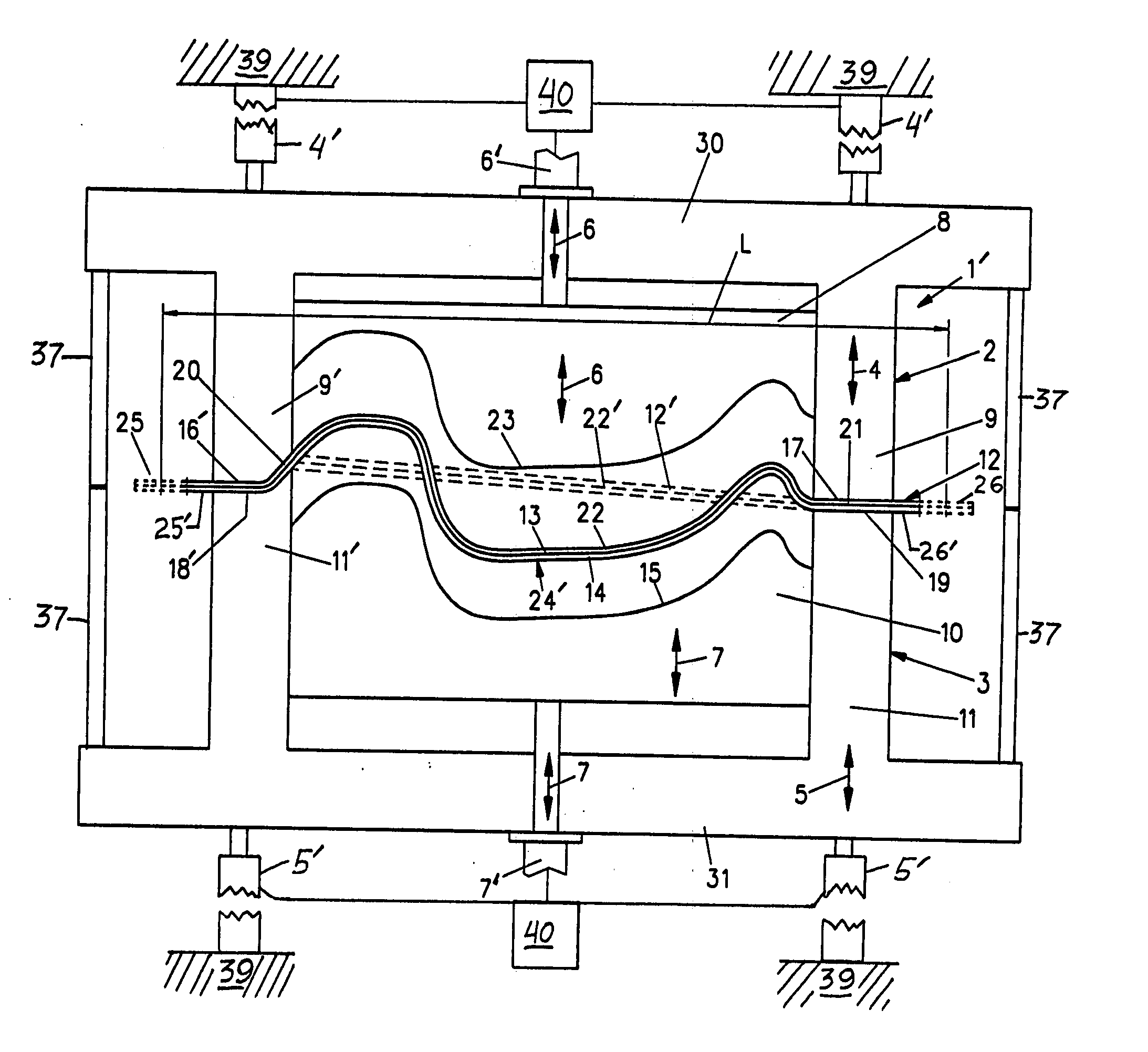
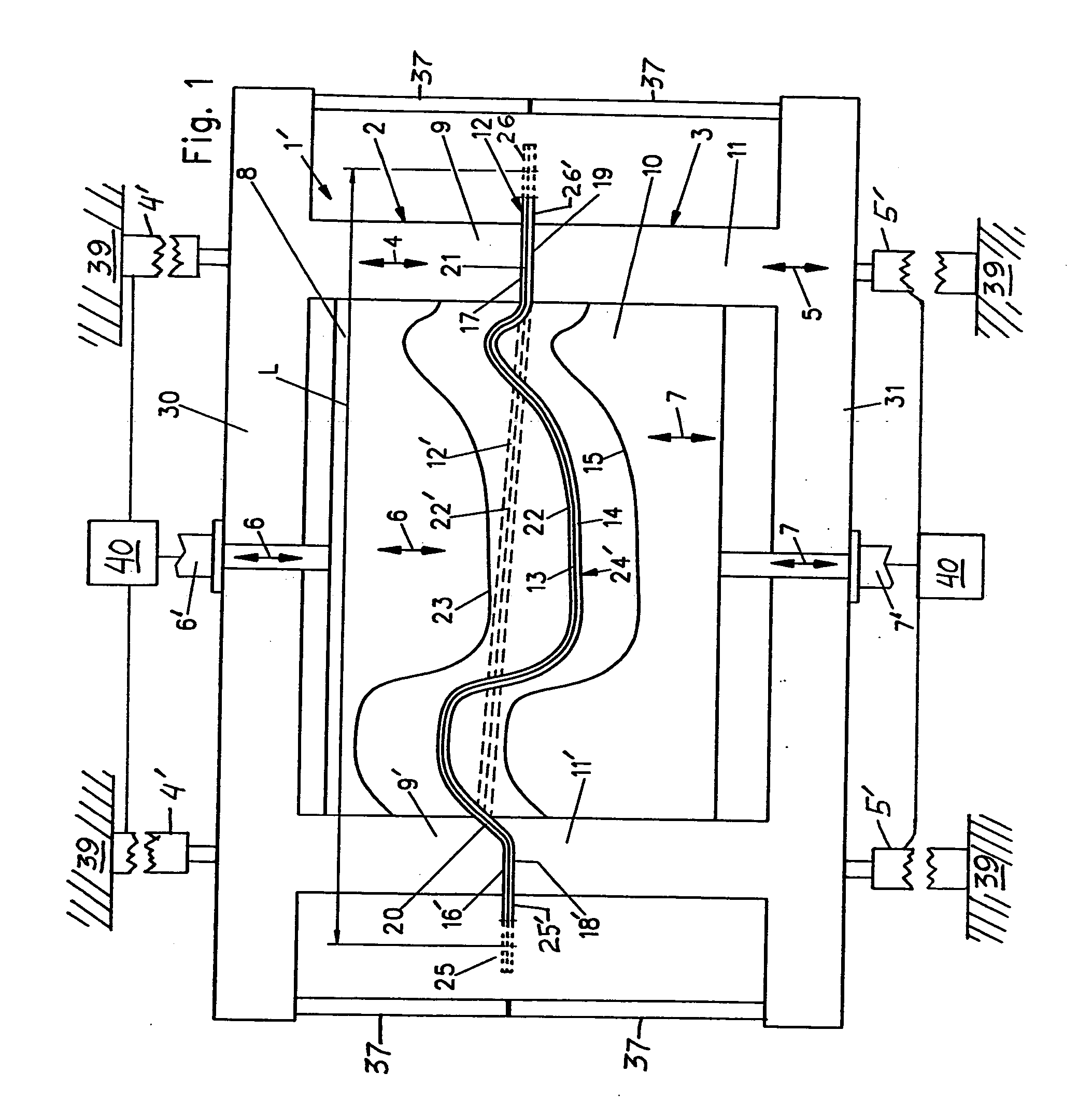
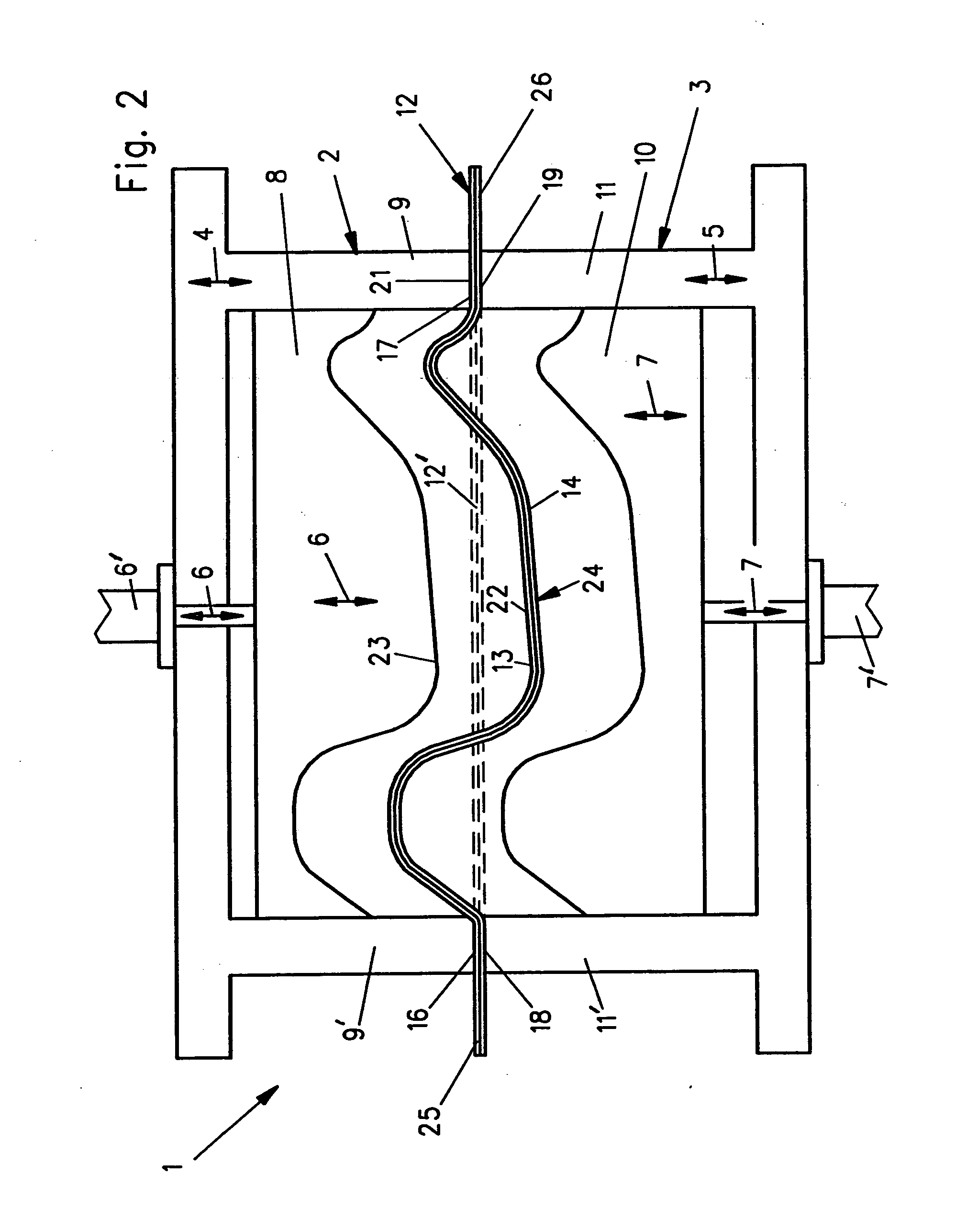
[0023]FIGS. 1 and 2 are basically similar schematic diagrams of two slightly different variants of a molding apparatus 1, 1′ according to the invention. First the similar or consistent features of the apparatuses 1 and 1′ will be described, and then the difference will be described.

[0024] The apparatus 1, 1′ comprises a structural machine frame 39 supporting an upper or first mold tool 2, and a lower or second mold tool 3, which are movable relative to one another and relative to the machine frame 39. More particularly, the upper or first mold tool 2 includes a main mold or inner core mold 8 and at least one outer frame or outer edge mold 9, 9′ arranged at at least one lateral edge or a perimeter of the inner core mold 8. Similarly, the lower or second mold tool 3 includes an inner core mold 10 and at least one outer edge mold 11, 11′ arranged at at least one lateral edge or a perimeter of the inner core mold 10. The outer edge mold or molds 9, 9′ can extend continuously around the...


PUM

PropertyMeasurementUnit
Lengthaaaaaaaaaa
Sizeaaaaaaaaaa
Forceaaaaaaaaaa

Abstract

An apparatus for producing a molded product from a sheet-form raw material blank has first and second mold tools that each respectively include a respective inner core mold and a respective outer edge mold laterally adjacent thereto. Drive elements drive the outer edge molds relative to a machine frame, and drive the inner core molds relative to the outer edge molds. A molding process involves closing the outer edge molds to hold an edge rim of the material blank while allowing slippage thereof, and then closing the inner core molds to three-dimensionally deform and mold a central portion of the material blank while pulling required additional material by slippage through the outer edge molds. A separate slip frame is not used. The edge rim held by the outer edge molds remains as a permanent mounting rim or flange of the finished molded product. Edge waste is minimized.

Description

PRIORITY CLAIM [0001] This application is based on and claims the priority under 35 U.S.C. §119 of German Patent Application 10 2004 034 792.1, filed on Jul. 19, 2004, and European Patent Application 0 50 04 510.3, filed Mar. 2, 2005, the entire disclosures of both of which are incorporated herein by reference. FIELD OF THE INVENTION [0002] The invention relates to a method and an apparatus for molding products, such as interior trim components for motor vehicles, from multi-layered sandwich laminate raw material blanks. BACKGROUND INFORMATION [0003] It is well known to produce laminated molded products, such as interior trim components for motor vehicles, from raw material blanks or webs or mats of multi-layered raw material, for example including thermoplastic fibers that serve as a thermoplastic meltable adhesive and matrix, as well as other fibers serving as a reinforcement or filler. A great variety of different methods and apparatuses for molding such a multi-layered raw mater...

Claims


Application Information

Patent Timeline
IPC IPC(8): B29C43/02
CPCB29C33/20B29C43/36B29L2031/3041B29K2105/0854B29C2043/3602
Inventor SPENGLER, GERHARD
Owner HERBERT OLBRICH
Why Eureka
Try Eureka