
Retrofittable severe duty seal for a shaft

a shaft and severe duty technology, applied in the direction of engine seals, mechanical equipment, engine components, etc., can solve the problems of unable to fit into all machine locations, and limiting the use of dual cone face seals, so as to achieve less susceptible, less sealing force, and more lips

Inactive Publication Date: 2006-01-19
DICHTOMATIK AMERICAS
View PDF77 Cites 23 Cited by
  • Summary
  • Abstract
  • Description
  • Claims
  • Application Information

AI Technical Summary

Benefits of technology

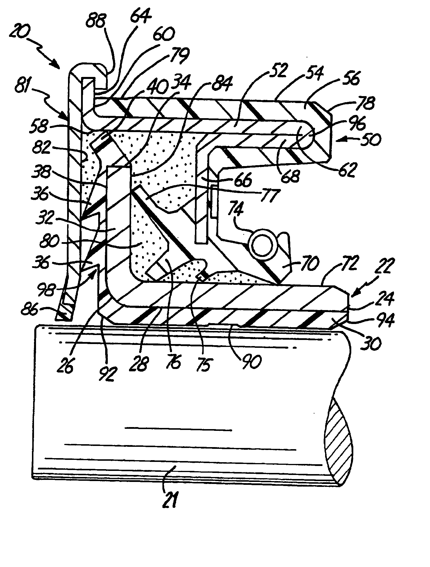
[0015] The availability of a seal having the superior performance characteristics of an embodiment according to the present disclosure in a package the size of ordinary seals gives additional freedom to designers of heavy machinery and severe duty assemblies. Many new design possibilities are made available by this seal because of the unitized style of the seal and the small width requirements as compared to dual cone face seals.
[0016] An important benefit of the seal disclosed is that it can create permanently lubricated shaft and bearing assemblies that can withstand severe use. This seal may enable equipment manufacturers to improve the performance of their machinery by reducing maintenance requirements. It is believed that existing vehicles and other machines can be retrofitted advantageously by replacing the original re-greasable seals with this new permanently lubricated seal. The lifetime of the new seal can last substantially longer than current lip seals. It is to be understood, however, that the present seal can be used to seal in either oil or grease and to substantially exclude all environmental contaminants that do not attack the materials from which the seal is manufactured.

Problems solved by technology

It is known by those in the art that dual cone face seals have the disadvantage of overall size that significantly restricts their use.
Dual cone face seals cannot fit into all of the machine locations because of design constraints.

Method used


Image

  • Retrofittable severe duty seal for a shaft
  • Retrofittable severe duty seal for a shaft
  • Retrofittable severe duty seal for a shaft

Examples


Embodiment Construction

[0043] The following description of the preferred embodiment(s) is merely exemplary in nature and is in no way intended to limit the invention, its application, or uses.

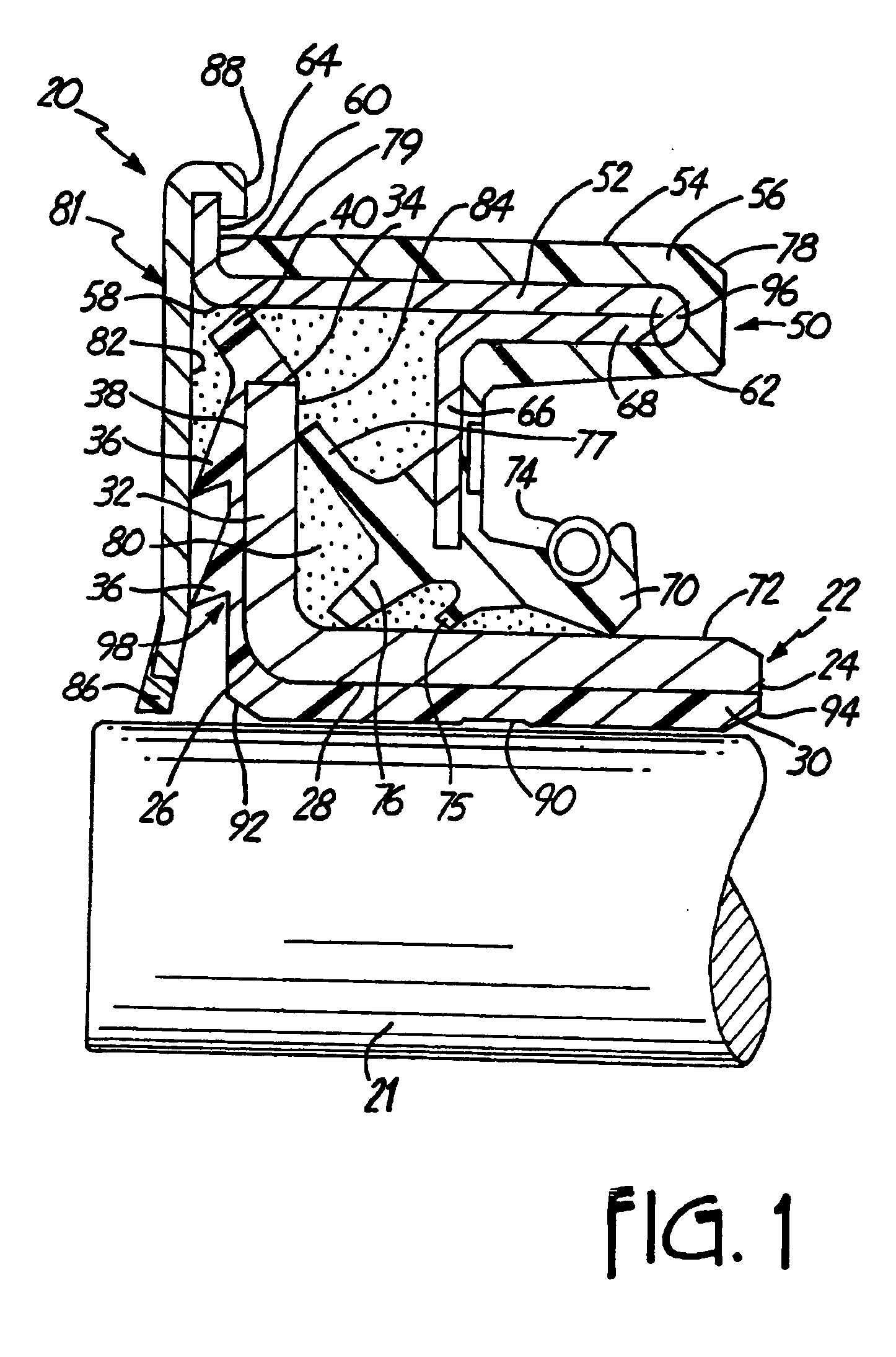
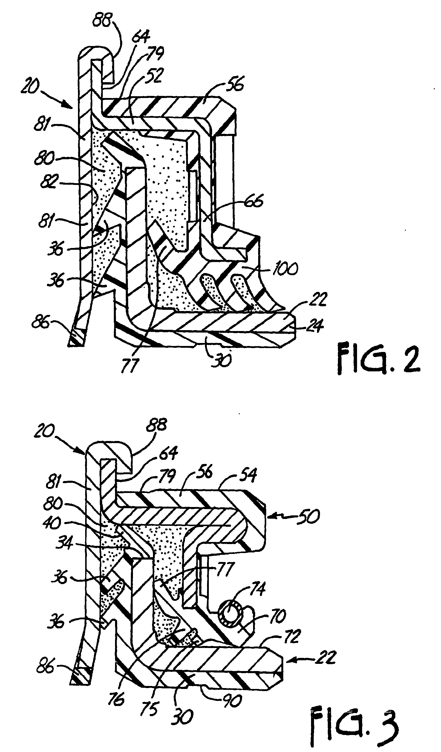
[0044] Referring now to the various figures of the accompanying drawing, FIG. 1 depicts a cross-sectional profile of an embodiment of the retrofittable severe duty seal 20 fitted onto a shaft 21. A cylindrical sleeve 22 component is disposed coaxially over, and in contact with, the shaft 21 so that when installation is complete, the sleeve 22 is affixed to the shaft 21. The sleeve inner end 24 extends into the sealed region, normally a housing or containment for oil or grease used to lubricate gears, bearings, or other moving parts.

[0045] To simplify nomenclature in this specification, the side or end or surface of a component that is oriented toward the lubricants, lubricated components, or other media from which it is desired to exclude dust, water, mud, and other environmental contaminants may be referred to usi...


PUM


Abstract

The present invention discloses a seal and a method of sealing dynamic shaft applications. The seal comprises an inner portion, an outer portion, a faceplate, and at least one flexible member located between the inner and outer portions. The method comprises providing a dynamic shaft assembly containing a bore for receiving a seal, providing a unitized seal, and placing the unitized seal on the shaft, thus sealing the assembly so that lubricants may not escape, and foreign material may not enter. The unitized seal can provide permanently lubricated sealed bearings in severe service conditions such as rollers and idlers of track-driven vehicles and agricultural equipment.

Description

CROSS-REFERENCE TO RELATED APPLICATIONS [0001] This Application is a Divisional of U.S. patent application Ser. No. 09 / 855,001, filed May 14, 2001, which is a Continuation-in-Part of U.S. patent application Ser. No. 09 / 690,524, filed Oct. 17, 2000 (now U.S. Pat. No. 6,406,026, issued Jun. 18, 2002), which is a continuation of U.S. application Ser. No. 08 / 937,427, filed Sep. 25, 1997 (now U.S. Pat. No. 6,186,507, issued Feb. 13, 2001); and U.S. patent application Ser. No. 09 / 855,001, filed May 14, 2001 is also a continuation-in-part of U.S. patent application Ser. No. 09 / 618,619, filed Jul. 18, 2000 (now U.S. Pat. No. 6,466,228, issued Oct. 15, 2002), which is a continuation-in-part of U.S. patent application Ser. No. 09 / 401,570, filed Sep. 22, 1999 (now U.S. Pat. No. 6,315,296, issued Nov. 13, 2001), which is a continuation-in-part of U.S. application Ser. No. 08 / 937,427, filed Sep. 25, 1997 (now U.S. Pat. No. 6,186,507, issued Feb. 13, 2001), all of the above which are herein incor...

Claims


Application Information

Patent Timeline
Patent Type & Authority Applications(United States)
IPC IPC(8): F16J15/32
CPCF16J15/3256
Inventor OLDENBURG, MICHAEL R.
Owner DICHTOMATIK AMERICAS
Learn More