
Method and apparatus for characterizing a signal path carrying an operational signal

a signal path and operational signal technology, applied in the direction of error prevention, digital transmission, instruments, etc., can solve the problems of difficult detection of faults, difficult detection of wires in electronic systems, and difficult resolution of most difficult wiring problems, etc., to achieve the effect of difficult detection

Active Publication Date: 2006-01-19
UNIV OF UTAH RES FOUND
View PDF13 Cites 56 Cited by
  • Summary
  • Abstract
  • Description
  • Claims
  • Application Information

AI Technical Summary

Benefits of technology

[0011] It has been recognized it would be advantageous to develop a reliable, easy-to-use, cost effective, and accurate system for characterizing wires that does not require taking a system out of service in order to perform testing of a wire. By performing live testing, detection of intermittent faults is enhanced. Because the tests can be performed continuously, intermittent faults, such as open circuits, short circuits, and arc faults, can be detected and recorded when they occur, enabling maintenance to quickly identify the nature and location of intermittent wiring problems so they can be resolved

Problems solved by technology

Cables (or synonymously, wires) are used as signal paths in many pieces of equipment that can have catastrophic results if the equipment fails.
However, the consequences of non-performance do not have to be so dire in order to see that benefits are still to be gained. infrastructure of buildings and homes, where they are difficult to reach.
Testing of wires in electronic systems can be difficult, however, as the wires are often inaccessible, hidden behind panels, wrapped in protective jackets, or otherwise difficult to access.
Removal of wires for testing or inspection can cause harm, and even if the wires are functioning properly upon testing or inspection, reinsertion of the wires into the system can result in damage.
Furthermore, among the most difficult wiring problems to resolve are those involving intermittent faults.
Because of their intermittent nature, such faults are difficult to detect.
Intermittent faults can result in circuit breaker trips, particular for new smart circuit breaker technology, yet finding the source of the failure can be very difficult.
Visual inspection, when possible, can fail when arc faults are too small to be detected visually.
A new type of circuit breaker, know as an arc fault circuit breaker, may actually exacerbate the challenges of detecting intermittent faults.
But, because the circuit breaker will open before damage becomes significant, the damage can be hidden making it more difficult to detect.
Also troublesome is that arc fault circuit breakers are a new technology, and may not work reliable, forcing wasted test time chasing problems that don't actually exist.
Finding these intermittent faults can be time consuming or even impossible using present techniques.
The duration of an arc fault can be as short at 5 to 20 ms, making it virtually impossible to find using conventional testing techniques.
Productive time is lost when systems must be taken out of service, yet the failures cannot be duplicated.

Method used


Image

  • Method and apparatus for characterizing a signal path carrying an operational signal
  • Method and apparatus for characterizing a signal path carrying an operational signal
  • Method and apparatus for characterizing a signal path carrying an operational signal

Examples


Embodiment Construction

[0027] Reference will now be made to the exemplary embodiments illustrated in the drawings, and specific language will be used herein to describe the same. It will nevertheless be understood that no limitation of the scope of the invention is thereby intended. Alterations and further modifications of the inventive features illustrated herein, and additional applications of the principles of the inventions as illustrated herein, which would occur to one skilled in the relevant art and having possession of this disclosure, are to be considered within the scope of the invention.

[0028] It is to be understood that, although this description is focussed on one particular exemplary application, the testing of a wire, various other applications of the inventive principles described herein are also possible some of which are discussed in further detail below. In general, distance measurement, length measurement, and impedance measurement may all be accomplished through the inventive techniq...


PUM


Abstract

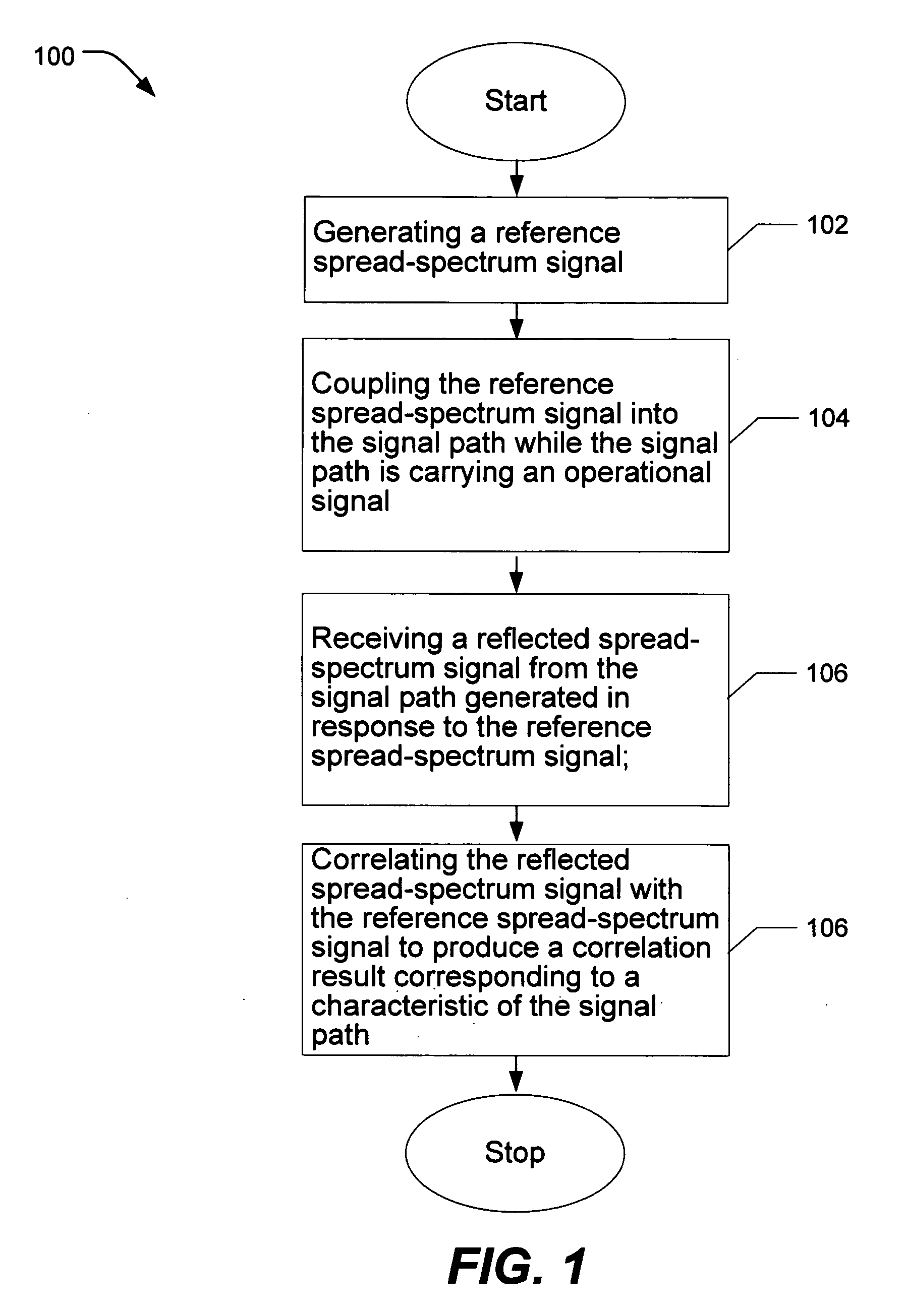
A method of characterizing a signal path comprising (i) generating 102 a reference spread-spectrum signal; (ii) coupling 104 the reference spread-spectrum signal into the signal path while the signal path is carrying an operational signal; (iii) receiving 106 a reflected spread-spectrum signal from the signal path generated in response to the reference spread-spectrum signal; and (iv) correlating 108 the reflected spread-spectrum signal with the reference spread-spectrum signal to produce a correlation result corresponding to a characteristic of the signal path.

Description

CROSS-REFERENCE TO RELATED APPLICATIONS AND CLAIM OF PRIORITY [0001] This application is a continuation-in-part of copending PCT Application No. PCT / US2004 / 003343 filed on 4 Feb. 2004 entitled “Method and Apparatus for Characterizing a Signal Path Carrying an Operational Signal” which claims the benefit of U.S. Application No. 60 / 444,761 filed on 4 Feb. 2003 entitled “Method and Apparatus for Characterizing a Signal Path Carrying an Operational Signal” and PCT Application No. PCT / US03 / 37233 filed on 19 Nov. 2003 entitled “Device and Method for Detecting Anomolies in a Wire and Related Sending Methods” which claims the benefit of U.S. Application No. 60 / 427,737 filed on 19 Nov. 2002 entitled “Handheld Device for Detecting Open, Short and Location of Anomaly on a Wire,” U.S. Application No. 60 / 455,788 filed on 18 Mar. 2003 entitled Noise Domain Reflectometer Apparatus and Method for Determining the Integrity and / or Lengths of Signal Paths,” U.S. Application No. 60 / 459,482 filed on 31 ...

Claims


Application Information

Patent Timeline
IPC IPC(8): G01R31/11
CPCG01R31/008G01R31/11H04L25/085H04B2201/709709H04L1/242H04B1/707
Inventor FURSE, CYNTHIASMITH, PAUL
Owner UNIV OF UTAH RES FOUND
Learn More