Outdoor-installed power conditioner device

a power conditioner and installation method technology, applied in the direction of power cables, electrical apparatus casings/cabinets/drawers, insulated conductors, etc., can solve the problems of increased manufacturing cost, decreased workability of attaching lids, and worker's accidental touch or damage of power converters, so as to reduce the number of members required

Active Publication Date: 2006-01-19
SHARP KK +1
View PDF8 Cites 16 Cited by
  • Summary
  • Abstract
  • Description
  • Claims
  • Application Information

AI Technical Summary

Benefits of technology

[0049] Preferably, the air exhausted from the first exhaust vent is guided by a backside of an inclined top panel forming the top face of the exhaust channel forming member, and introduced to a lower part of the exhaust channel. According to the outdoor-installed power conditi

Problems solved by technology

Such an increase in the number of screws 204 causes problems of an increase in manufacturing cost and a decrease in workability of attaching lid 203 to outer case 202.
If the work for connecting the interconnections is carried out in such a situation, the worker may accidentally touch or damage power converter 206.
However, in conventional outdoor-installed power conditioner 301, the direction in which the air blown out by fan 316 flows is relatively perpendicular to the direction in which the air exhausted from exhaust vent 306 flows, and thus the air taken in by

Method used


Image

  • Outdoor-installed power conditioner device
  • Outdoor-installed power conditioner device
  • Outdoor-installed power conditioner device

Examples


first embodiment

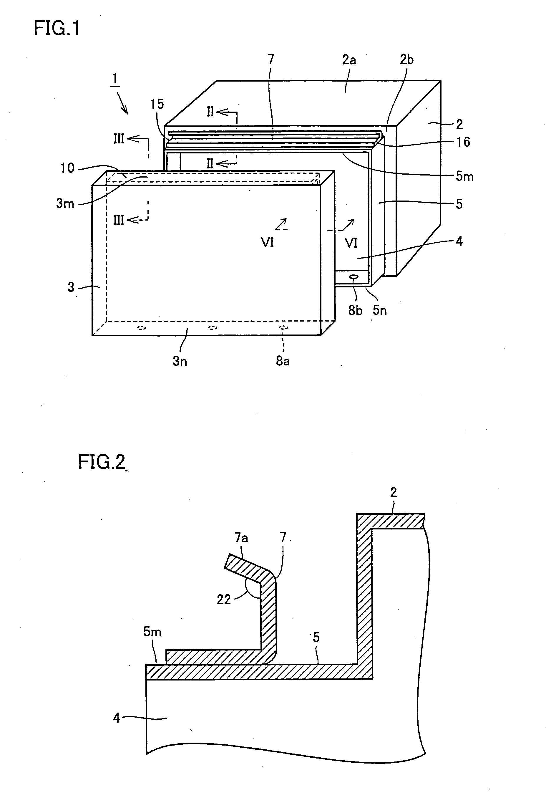
[0077]FIG. 1 is a perspective view showing an enclosure for an outdoor-installed power conditioner in a first embodiment of the present invention. Referring to FIG. 1, an enclosure 1 housing a power converter installed outdoors includes an outer case 2 and a lid 3. Outer case 2 and lid 3 are made of a metal material. Outer case 2 and lid 3 are formed so as to have equal-sized attachment faces to eliminate difference in level on the surface of enclosure 1, improving the appearance of enclosure 1.

[0078] An opening 4 is provided in a front face 2b, one of the four side faces of outer case 2. Along the periphery of opening 4, an outer peripheral portion 5 is formed so as to project from front face 2b. On a top face 5m of outer peripheral portion 5, a plate member 7 is provided extending from one end 15 to the other end 16 of top face 5m. In a bottom face 5n of outer peripheral portion 5, a plurality of screw holes 8b for fastening lid 3 to outer case 2 are formed. It is to be noted tha...

second embodiment

[0091]FIG. 9 is a perspective view showing an enclosure for an outdoor-installed power conditioner in a second embodiment of the present invention. Referring to FIG. 9, an enclosure 50 for a power conditioner for a photovoltaic power generation system includes an outer case 65 and a lid 66. Lid 66 includes a lid 66a as a first portion closing an upper part of outer case 65 and a lid 66b as a second portion closing a lower part of outer case 65. That is, lid 66b is provided at a position closer to the ground than lid 66a. Outer case 65 is identical to outer case 2 in the first embodiment except that a fastening plate 91 for attaching lid 66a is provided.

[0092] In lid 66a, a fastening plate 71 is provided at a position confronting lid 66b. On fastening plate 71, rectangular-shaped slits 72 are formed at a plurality of locations. At both ends of fastening plate 71, holes 73 for fastening lid 66a to outer case 65 are provided. Plate member 10 is provided as in lid 3 of the first embodi...

third embodiment

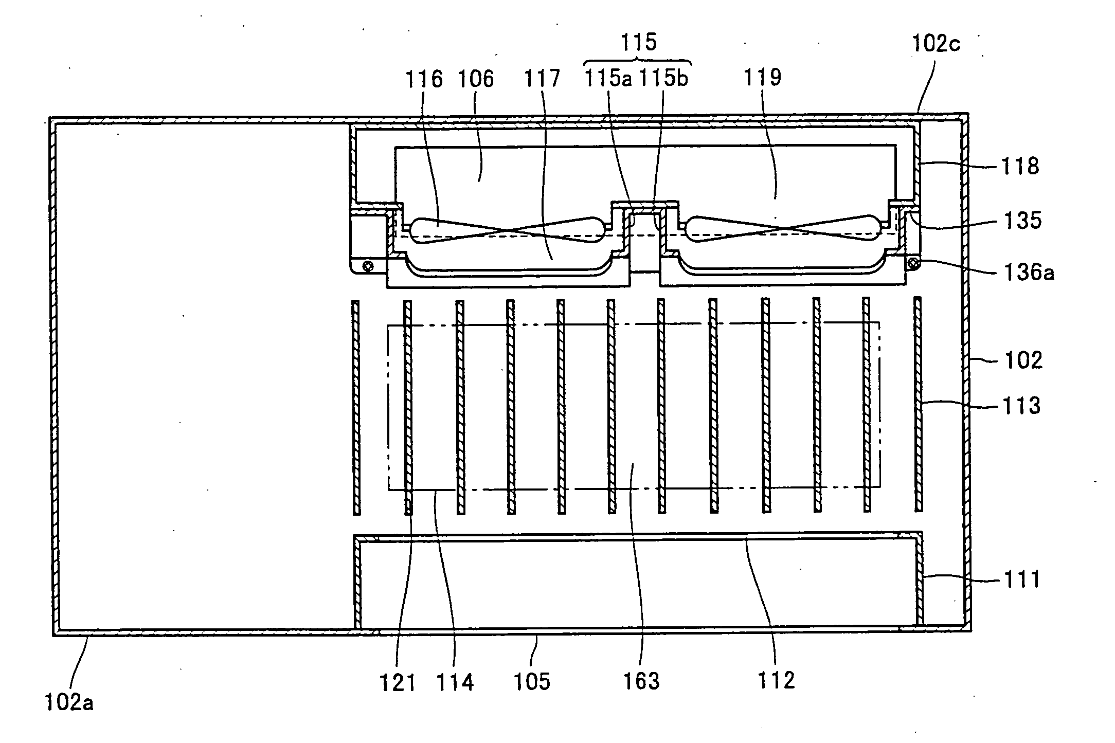
[0099] In the following, an outdoor-installed power conditioner in a third embodiment will be described with reference to the drawings. FIG. 13 is a perspective view seen from the front side showing a structure of an outdoor-installed power conditioner in the present embodiment.

[0100] Referring to FIG. 13, an outdoor-installed power conditioner 101 includes an outer case 102 constituting an enclosure and a lid 104 covering an opening provided on the front side of outer case 102. An exhaust channel forming member 103 is connected to the enclosure, and outdoor-installed power conditioner 101 is installed outdoors by mounting exhaust channel forming member 103 on an outer wall of a building. An intake vent 105 is provided in a bottom face 102a of outer case 102, and a first exhaust vent 106 is provided in a rear face 102b of outer case 102. Intake vent 105 is formed with rectangular holes arranged in a plurality of rows. Exhaust channel forming member 103 is provided on rear face 102b...


PUM


Abstract

An enclosure is formed of an outer case and a lid. The outer case includes a first projecting strip portion provided on a top face side of the outer case and on an outer peripheral portion defining an opening, and extending to project outwardly from the outer case, and the lid includes a second projecting strip portion provided at a position facing the first projecting strip portion. With the opening of the outer case closed with the lid, the first and second projecting strip portions make close contact with each other along a direction in which these portions extend. This structure can protect the inside from an external factor such as rainwater or dust.

Description

TECHNICAL FIELD [0001] The present invention relates to an outdoor-installed power conditioner converting direct current (DC) power produced by an independent DC power supply into alternating current (AC) power to supply the power to a general AC load for home and business use or to an existing commercial power system. BACKGROUND ART [0002] A solar battery is known as a simple and clean energy source without emitting toxic substances. Exposed to sunlight, it operates as a DC power supply and outputs DC power. A power conditioner for photovoltaic power generation system serves to convert DC power generated by a solar battery into AC power to supply the power to a general AC load or to an existing commercial power system. Since the solar battery is installed at a location receiving sunlight, such as on a roof of a house, the power conditioner for photovoltaic power generation system is also installed outdoors in many cases. [0003] To protect such an outdoor-installed power conditioner...

Claims


Application Information

Patent Timeline
IPC IPC(8): H02B1/00H02B1/28H05K5/06H05K7/20
CPCH02B1/28H05K7/20154H05K5/063
Inventor NAKATA, HIROFUMIHIROSE, NAOTOSAKAMOTO, YUKITAKA
Owner SHARP KK
Why Eureka
Try Eureka