Packet generating method, video decoding method, media multiplexer, media demultiplexer, multimedia communication system and bit stream converter

a packet generation and video decoding technology, applied in the field of video packet generating methods, video decoding methods, media multiplexers, media demultiplexers and multimedia communication systems, can solve the problems of inability to effectively convert error resistance syntax between, inability to specify the macroblock in which the error has occurred and the information, and prior art failure to practice error concealment. the effect of recovery

Inactive Publication Date: 2006-01-19
MITSUBISHI ELECTRIC CORP
View PDF6 Cites 55 Cited by
  • Summary
  • Abstract
  • Description
  • Claims
  • Application Information

AI Technical Summary

Benefits of technology

[0016] It is therefore an object of the present invention to provide a media multiplexer, a moving image decoder and a multimedia communication system which permit easy recovery from errors in the decoding of coded video streams by multiplexing their important in

Problems solved by technology

Hence, when pieces of coded data of plural macroblocks are combined into one packet AL-SDU, it can be known from the result of error detection that there is an error in any one of the plural macroblocks contained in the packet AL-SDU, but it is impossible to specify the macroblock in which the error has occurred and the information in which the error has occurred.
Accordingly, the prior art fails to practice error concealment by mak

Method used


Image

  • Packet generating method, video decoding method, media multiplexer, media demultiplexer, multimedia communication system and bit stream converter
  • Packet generating method, video decoding method, media multiplexer, media demultiplexer, multimedia communication system and bit stream converter
  • Packet generating method, video decoding method, media multiplexer, media demultiplexer, multimedia communication system and bit stream converter

Examples


embodiment 1

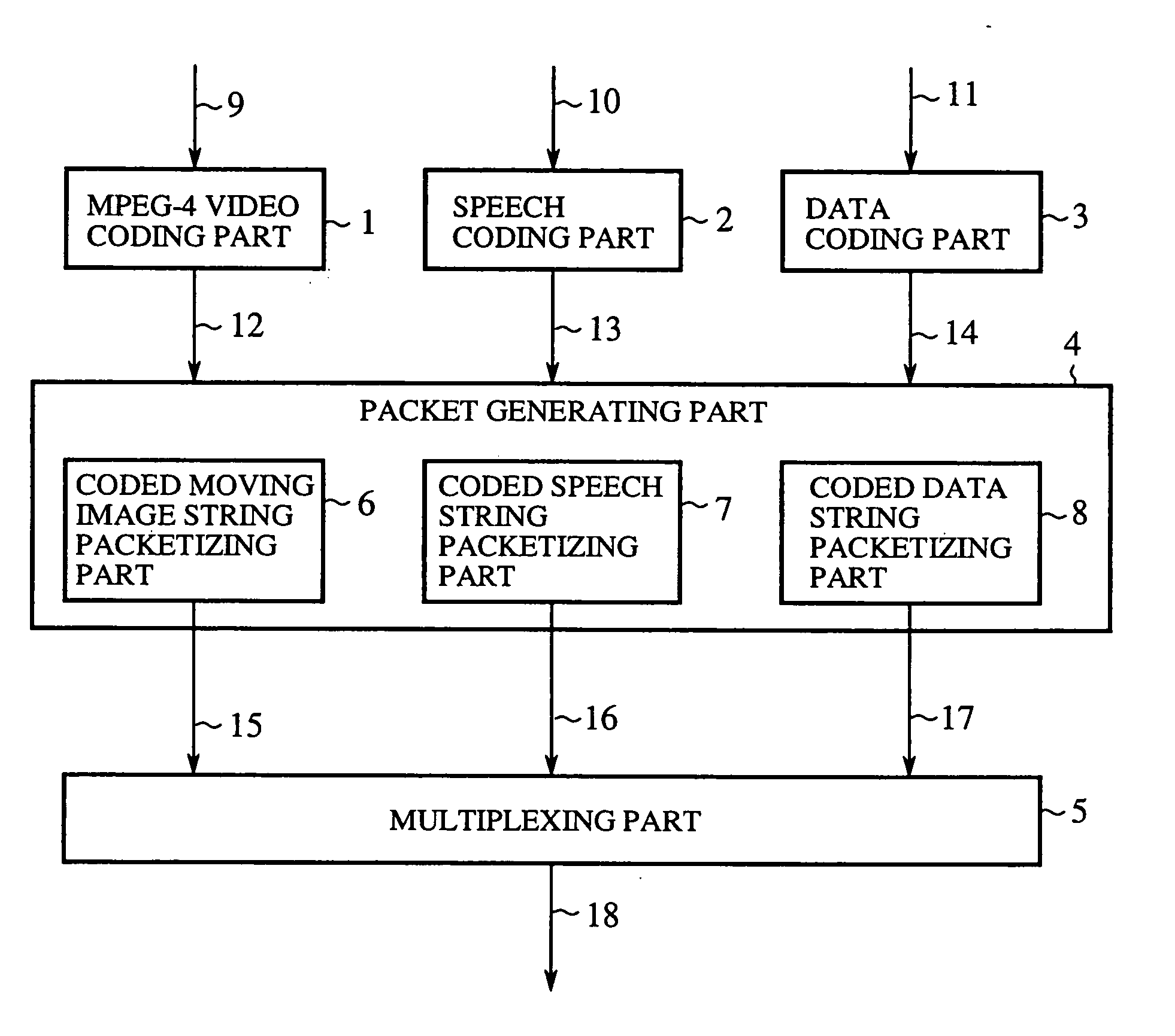
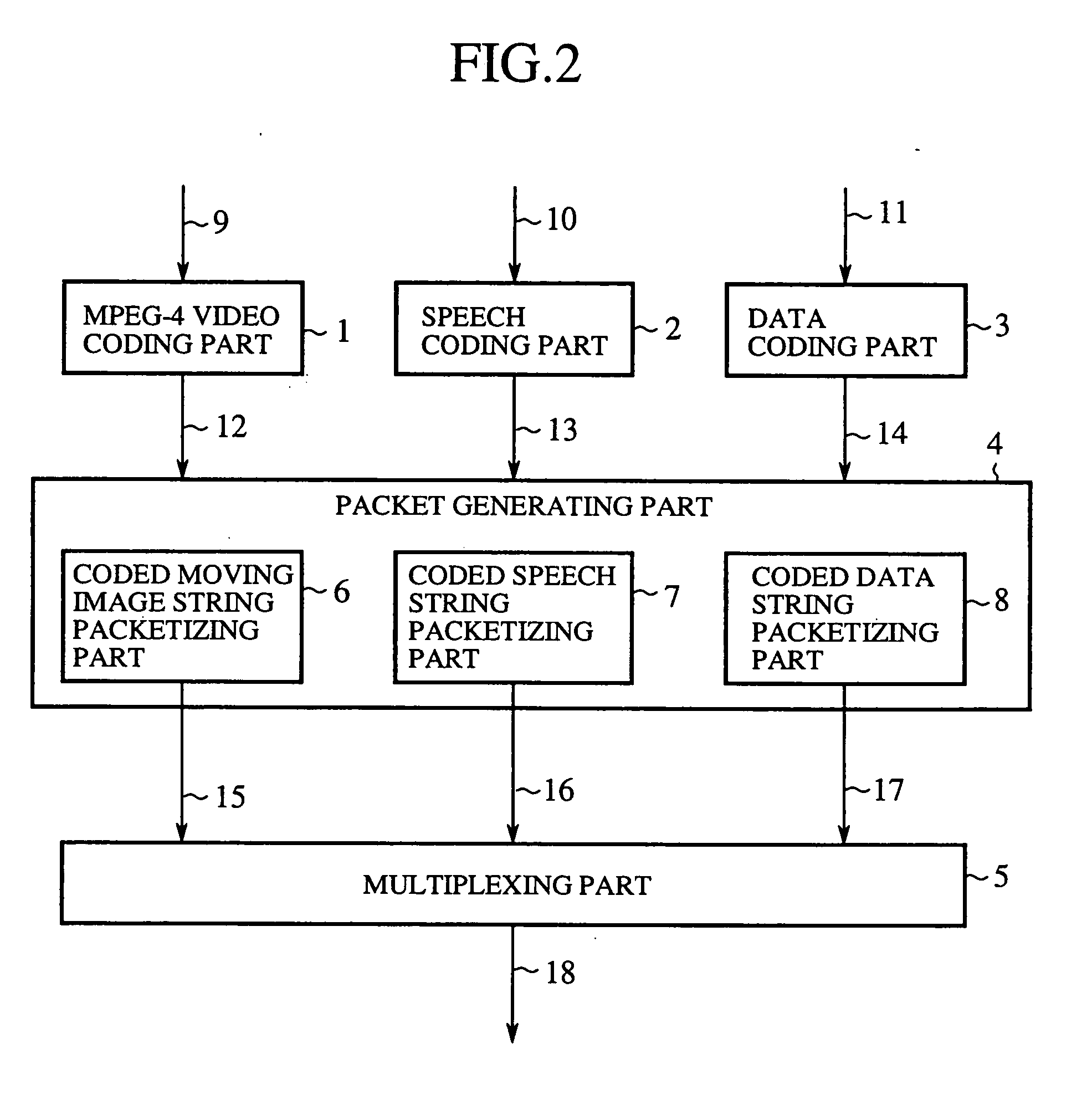
[0086]FIG. 2 is a block diagram illustrating a transmitting apparatus of a multimedia communication system according to a first embodiment (Embodiment 1) of the present invention in which a coded video stream, encoded by the MPEG-4 coding system (ISO / IEC 14496-2), is multiplexed by H. 223 together with coded speech and data streams at the transmitting side and transmitted therefrom and at the receiving side the multiplexed stream is demultiplexed into the original speech, video and data. Reference numeral 1 denotes an MPEG-4 video coding part; 2 denotes a speech coding part; 3 denotes a data coding part; 4 denotes a packetizing part; 5 denotes a multiplexing part; 6 denotes a coded video stream packetizing part; 7 denotes a coded speech stream packetizing part; 8 denotes a coded data stream packetizing part; 9 denotes an input image signal; 10 denotes an input speech signal; 11 denotes an input data signal; 12 denotes a coded video stream; 13 denotes a coded speech stream; 14 denote...

embodiment 2

[0132] This embodiment (Embodiment 2) concerns modifications of the coded video stream packetizing part 6 and the MPEG-4 video decoding part 1 used in Embodiment 1.

[0133] In this embodiment no particular limitations are imposed on the structure of the macro block data of the coded video stream that is output from the MPEG-4 video coding part 1. That is, the coded video stream shown in FIG. 3(a) may be the macro block data encoded using the data partitioning scheme defined by MPEG-4 as depicted in FIG. 3(b), or macro block data of a structure in which the macro block header, the motion information and the texture information are arranged for each of n macro blocks as depicted in FIG. 9. This embodiment does not impose any particular limitations on the macro block data structure as mentioned above, but the following description will be given on the assumption that the macro block data has the structure shown in FIG. 9.

[0134] The operation of the coded video stream packetizing part 6...

embodiment 3

[0165] This embodiment (Embodiment 3) is directed to another modification of the coded video stream packetizing part used in Embodiment 1.

[0166] The coded video stream packetizing part 6 in this embodiment is characterized in that the resynchronization marker, which is a particularly important one of the pieces of VP header information, and the macro block address are mapped into one packet (AL-SDU). That is, As referred to previously in Embodiment 2, the macro block address contained in the VP header information represents absolute position information of the macro block at the head of the video packet. Accordingly, when the macro block address is wrong, the decoded macro block is placed at a wrong position in the picture, resulting in the decoded image suffering a serious deterioration in image quality. To avoid this, in the coded video stream packetizing part 6 according to this embodiment, the resynchronization marker in the VP deader information and the macro block address are...


PUM


Abstract

A moving image coded string is mapped with a set of information areas as one packet, and each packet is added with an error code and control information in a multiplexing part so that it is decided at the receiving side, from the result of error detection by decoding the error detection code, whether an error has occurred in each information area of the packet.

Description

CROSS-REFERENCE TO THE RELATED APPLICATION [0001] This application is a continuation of International Application No. PCT / JP00 / 01009, whose International filing date is Feb. 22, 2000, the disclosures of which Application are incorporated by reference herein.BACKGROUND OF THE INVENTION [0002] 1. Field of the Invention [0003] The present invention relates to a video packet generating method, a video decoding method, a media multiplexer, media demultiplexer and a multimedia communication system which are used in the process of sending coded audio, video (moving image) and data packets as a multiplexed stream from the transmitting side and demultiplexing the multiplexed stream into audio, video and data at the receiving side. Furthermore, the present invention also pertains to a bit stream converter which permits effective conversion of an error resistance syntax according to the channel condition. [0004] 2. Description of the Prior Art [0005] To facilitate a better understanding of the...

Claims


Application Information

Patent Timeline
IPC IPC(8): H04B1/66H04N11/02H04N11/04H04N7/12
CPCH04N21/234309H04N21/4341H04N21/2402H04N21/2368
Inventor SEKIGUCHI, SHUNICHIOGAWA, FUMINOBUASAI, KOHTAROISU, YOSHIMIKURODA, SHINICHIHASEGAWA, YURI
Owner MITSUBISHI ELECTRIC CORP
Why Eureka
Try Eureka