Rotating anode X-ray tube and X-ray generator

a technology of rotating anodes and generators, which is applied in the direction of x-ray tube gas control, electric discharge tubes, electrical apparatus, etc., can solve the problems of shortening the lifetime of parts, reducing so as to prolong the service life of parts

Active Publication Date: 2006-01-19
RIGAKU CORP
View PDF14 Cites 26 Cited by
  • Summary
  • Abstract
  • Description
  • Claims
  • Application Information

AI Technical Summary

Benefits of technology

[0015] A rotating anode X-ray tube according to the present invention has the advantages described below. Air in the air passage formed in the casing is discharged to the atmosphere with the rotary vane, so that the cooling water leaking in the air passage in the form of vapor or atomized droplets can be soon discharged to the atmosphere. Therefore, vapor is prevented from condensing on parts such as a bearing, an electric brush or a vacuum sealing device, housed in the casing to prolong the lifetime of the parts. Further, there is provided a coolant sensor communicating with the air passage in addition to the rotary vane, so as to detect cooling water leaking from the rotary liquid-tight sealing device, to prompt an operator to exchange the rotary fluid-tight sealing device. Additionally, even when the rotary vane is omitted to use only the humidity sensor, a trace of water leakage can be detected.

Problems solved by technology

When the liquid-tight property has been deteriorated because of roughness or wear of the seal surface, water leakage occurs little by little.
When the leakage water adheres to parts such as a bearing, an electric brush or a vacuum sealing device, the lifetime of the parts would be shortened disadvantageously.
The above-described water leakage sensor, however, can not cope with water leakage little by little caused by deterioration of a coolant sealing device.
When such water leakage occurs, the lifetime of parts, such as a bearing, an electric brush or a vacuum sealing device, housed in the casing is shortened disadvantageously as has been described above.
The water leakage sensor disclosed in the second publication can not cope with such water leakage.
The type of water leakage sensor which stores water in a tray can not always detect such water leakage and can not early detect a trace of water leakage.
At the stage of a trace of water leakage, it would be effective to let out water in the form of vapor to the atmosphere to prolong the lifetime of parts, but such a thing is impossible in the prior art disclosed in the second publication.

Method used


Image

  • Rotating anode X-ray tube and X-ray generator
  • Rotating anode X-ray tube and X-ray generator
  • Rotating anode X-ray tube and X-ray generator

Examples


Embodiment Construction

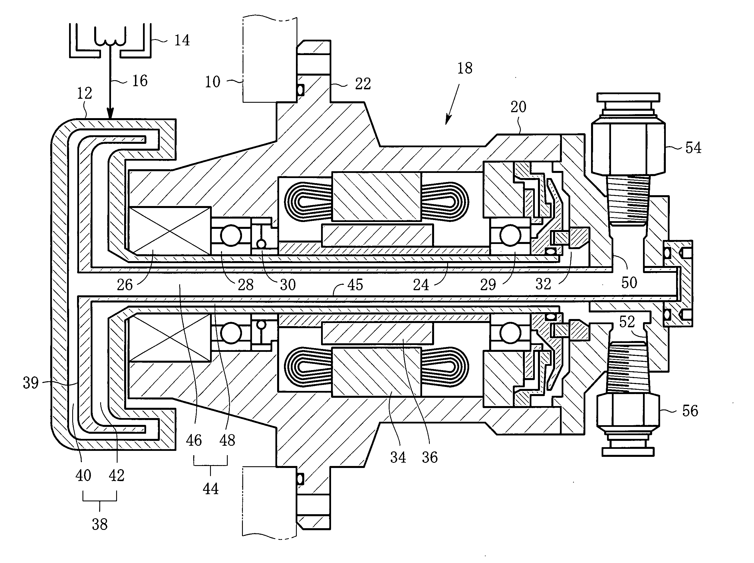
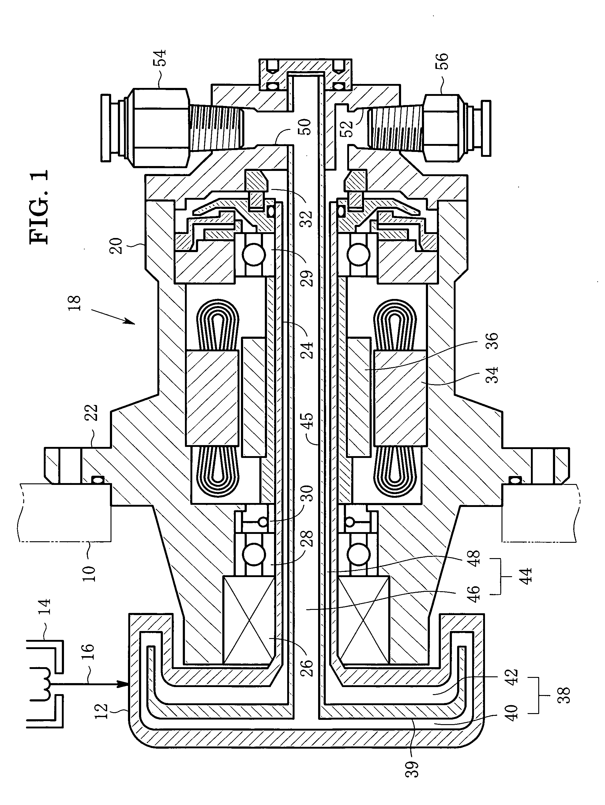
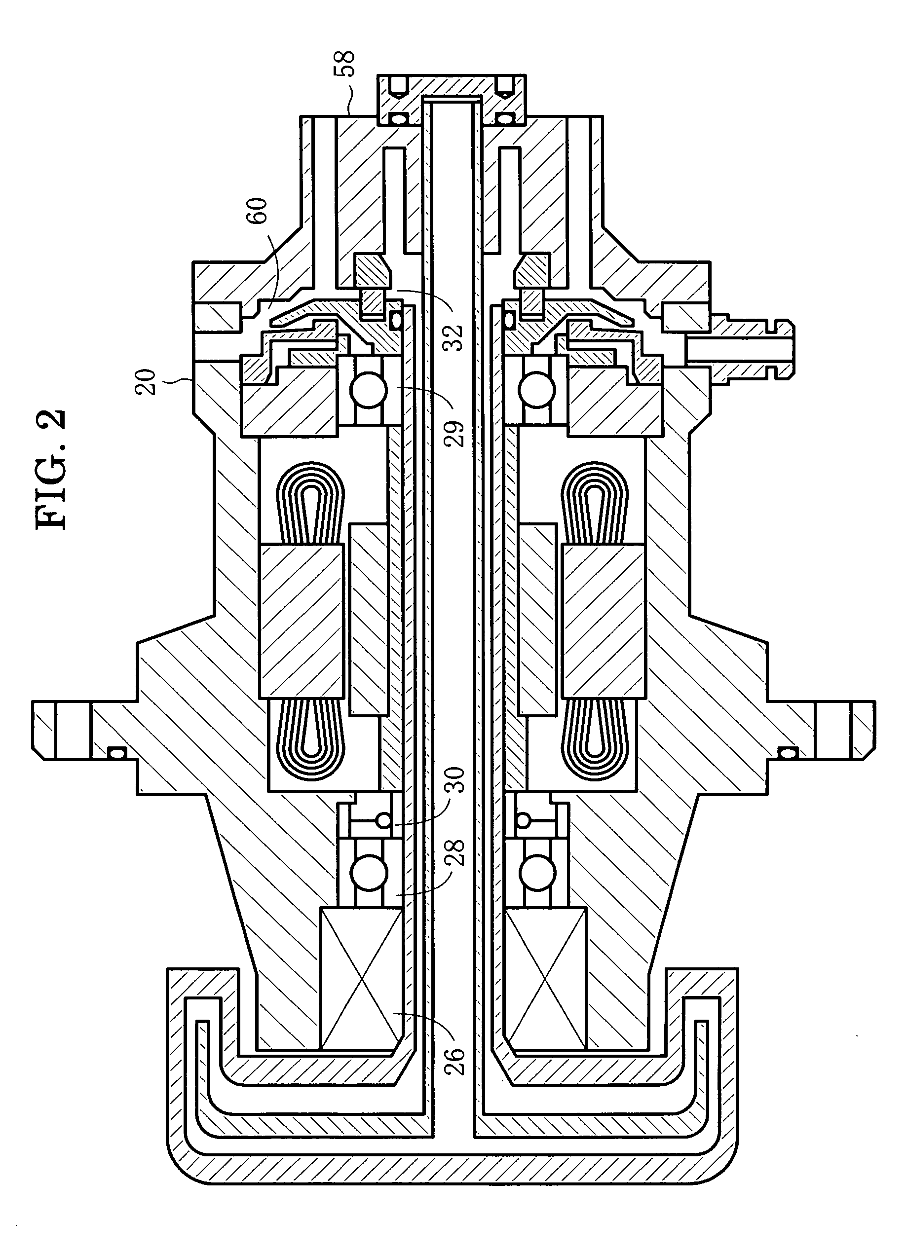
[0028] Embodiments of the present invention will now be described below with reference to the drawings. FIGS. 1 to 3 show the principal part of one embodiment of a rotating anode X-ray tube according the present invention. FIG. 1 is a sectional view taken along a plane including an axis of rotation of a rotating anode, especially showing clearly a coolant passage. FIG. 2 is a sectional view taken along another plane including the axis of rotation of the rotating anode, especially showing clearly an air passage. FIG. 3 is a rear view shown from the right in FIG. 1. FIG. 1 is a sectional view taken along the line 1-1 in FIG. 3, while FIG. 2 is a sectional view taken along the line 2-2 in FIG. 3.

[0029] Referring to FIG. 1, a rotating anode X-ray tube has a vacuum chamber 10, and has a rotating anode 12 and an electron gun 14 each housed in the vacuum chamber 10. A high voltage is supplied, from a high-voltage power supply, between the electron gun 14 and the rotating anode 12 to allow...


PUM


Abstract

A coolant passage is formed inside the rotary shaft while an air passage is formed inside the casing. A mechanical seal is arranged between the coolant passage and the air passage. Leakage cooling water, which has leaked in the form of vapor from the mechanical seal, is relegated radially outwardly along with air by the action of a rotary vane, which is disposed in the air passage, and finally flows out of an air outlet. A coolant sensor may be provided to early detect the leakage water.

Description

BACKGROUND OF THE INVENTION [0001] 1. Field of the Invention [0002] The present invention relates to a rotating anode X-ray tube which is capable of coping with the coolant leakage from a rotary seal, the coolant being for cooling the inside of the rotating anode, and also relates to an X-ray generator having such a rotating anode X-ray tube. [0003] 2. Description of the Related Art [0004] A rotating anode of a rotating anode X-ray tube is cooled at its inside by cooling water. Since the rotating anode is rotated during cooling by the cooling water, its coolant passage must be sealed by a rotary liquid-tight sealing device such as a mechanical seal or an oil seal. The sealing function of the sealing region is maintained by, in general, an elastic force. When the liquid-tight property has been deteriorated because of roughness or wear of the seal surface, water leakage occurs little by little. When the leakage water adheres to parts such as a bearing, an electric brush or a vacuum se...

Claims


Application Information

Patent Timeline
Patent Type & Authority Applications(United States)
IPC IPC(8): H01J35/10H01J35/26H01J35/24H01J35/28
CPCH01J35/101H01J2235/20H01J35/106H01J35/107H01J35/1024
Inventor SAKATA, MASATAKACHAKI, TOMOHIROOKAZAKI, MASARUKUSAKA, YUJIUMEGAKI, SHIROHAMANAKA, ATSUSHINONOGUCHI, MASAHIRO
Owner RIGAKU CORP
Why Eureka
Try Eureka