
Image processing device

a technology of image processing and processing device, which is applied in the field of image processing apparatus, an, can solve the problems of color jumping, and insufficient correction accuracy of the above-mentioned color correction

Inactive Publication Date: 2006-01-19
GK BRIDGE 1
View PDF8 Cites 86 Cited by
  • Summary
  • Abstract
  • Description
  • Claims
  • Application Information

AI Technical Summary

Benefits of technology

[0013] In consideration of the above-mentioned problems, the present invention is intended to provide an image processing apparatus, an image processing method, a program, a recording medium, a printer, a television receiver, a projector apparatus, a photographing apparatus and a mobile communication terminal not causing a side effect of correcting colors that should not be subjected to memory color correction essentially.
[0014] Furthermore, in consideration of the above-mentioned problems, the present invention is intended to provide an image processing apparatus, an image processing method, a program, a recording medium, a printer, a television receiver, a projector apparatus, a photographing apparatus and a mobile communication terminal capable of avoiding correcting other objects included in the memory color region that should be corrected essentially but accidentally having colors close to the color to be corrected.

Problems solved by technology

Since the color correction technologies required for numerous full-color devices, such as a camera, a display and a printer, more specifically, the color correction technologies of correcting the inherent characteristics of devices, such as the spectroscopic characteristic of a CCD in a camera and the spectroscopic characteristic of ink in a printer, were being developed, the correction accuracy of the above-mentioned color correction was insufficient; on the assumption of this, the technologies conventionally referred to as selective color adjustment and memory color correction were intended to correct improper color reproduction owing to the insufficient accuracy.
However, in the present circumstances where digital cameras are being widespread and being substituted for silver salt analog photographs, as high-quality picture technologies that were impossible for analog silver salt photographs, technologies of selective color adjustment and memory color correction having target levels higher than previous levels have become required.
Such a color becomes discontinuous at the boundary of the region and causes color jumping.
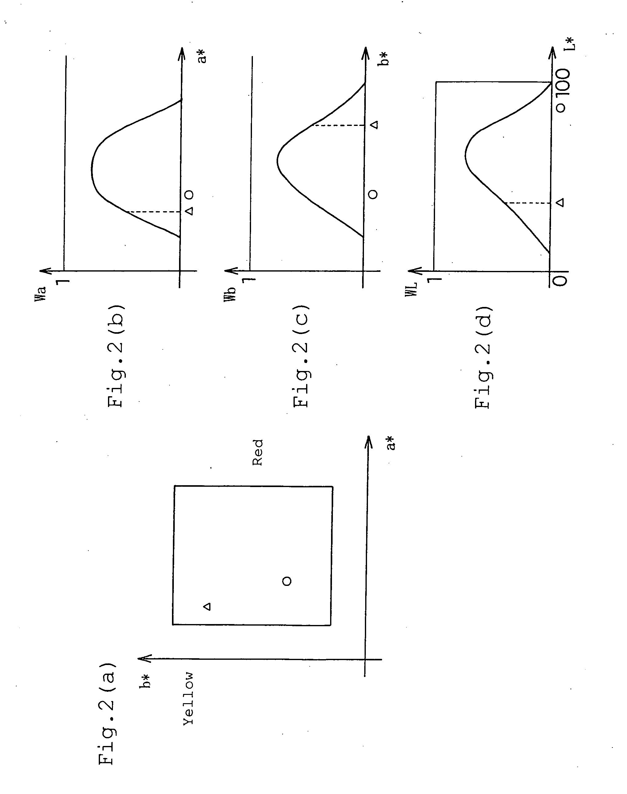
Hei 06-78320, a correction region and the weight of correction are calculated using the minimum value of two weighting functions being orthogonal in a chromaticity plane, and the hue, saturation and luminance are shifted by the amount proportional to the weight, whereby it can be expected to have an effect of memory color correction; however, because the correction is carried out in a rectangular region in the chromaticity plane, it is difficult to narrow the regions of skin color and sky blue necessarily and sufficiently; if the effect is exerted, a side effect of correcting colors that should not be changed essentially is caused.
Since the color correction technologies of correcting the inherent characteristics of devices were being developed as described above, the correction accuracy of the above-mentioned color correction was insufficient; on the assumption of this, the color regions unable to be corrected properly because of such reasons were corrected as a whole; it seems that there were no higher requests in those days.
Hence, a side effect of correcting colors that should not be corrected essentially is caused.
In addition, it is inevitable that other objects included in the memory color region that should be corrected essentially but accidentally having colors close to the color to be corrected are corrected.
Furthermore, gradation is apt to become discontinuous, and color jumping occurs, whereby image quality degradation may be caused, beyond the effect of memory color correction.

Method used


Image

  • Image processing device
  • Image processing device
  • Image processing device

Examples


embodiment 1

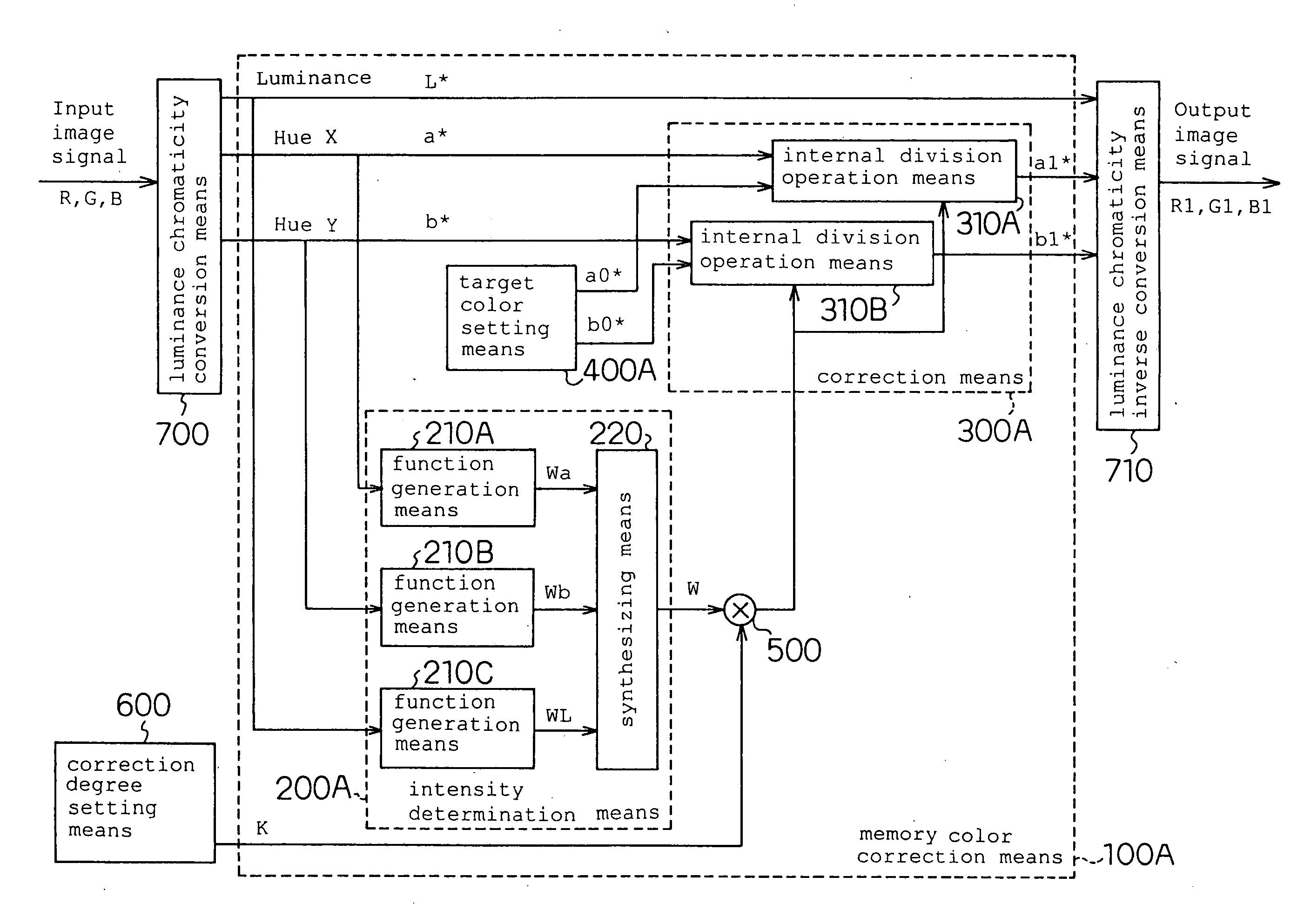
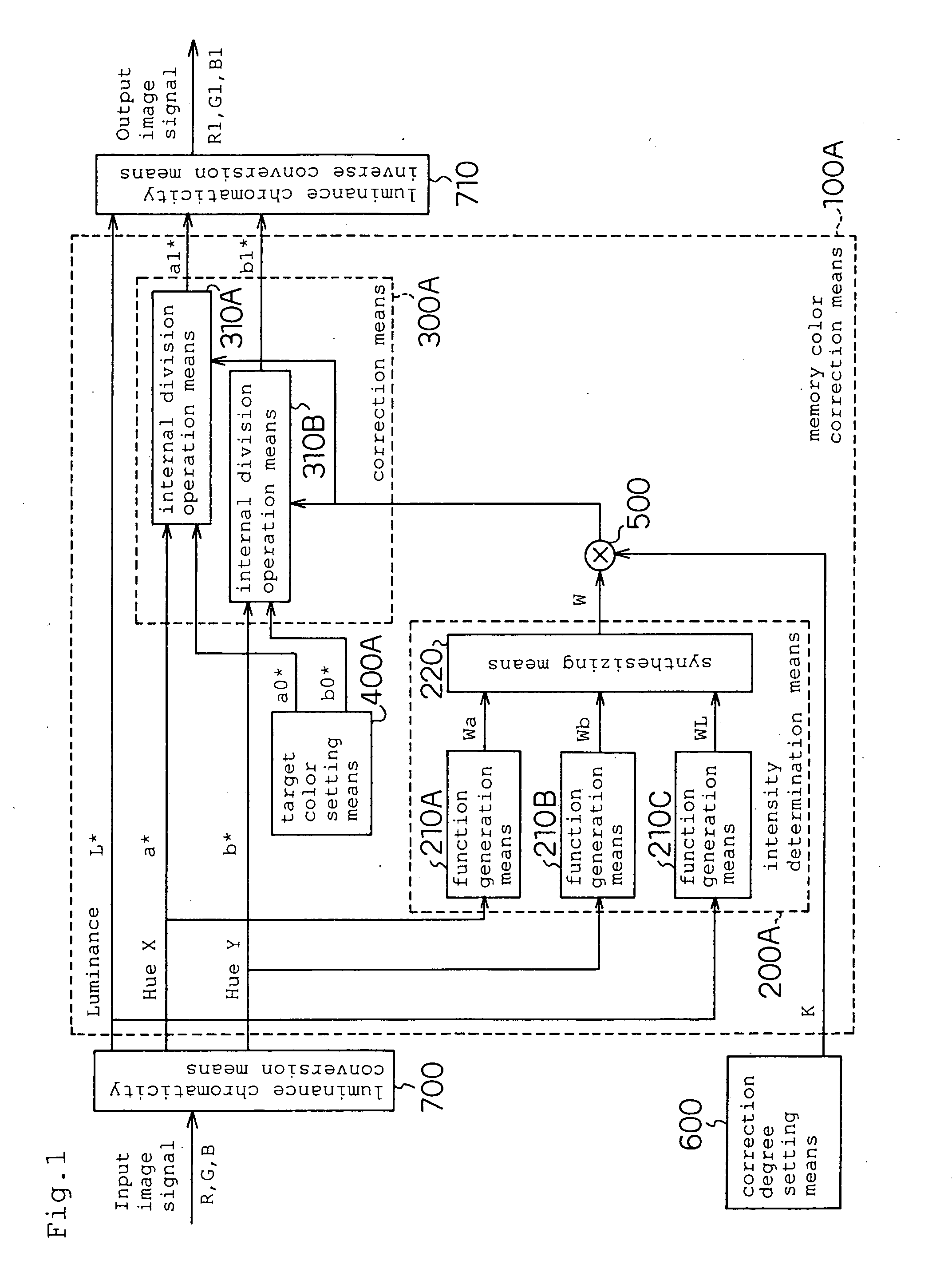
[0155]FIG. 1 is a block diagram showing a schematic configuration of an image processing apparatus in accordance with Embodiment 1 of the present invention. The image processing apparatus in accordance with this embodiment is configured as a unit of carrying out the memory color correction of skin color and installed in a color printer wherein a memory card storing images taken using a digital camera is input and digital photographs are printed. Hence, a card reader, a JPEG development processor, a page memory, a print engine, etc., not shown, other than the devices shown in this block diagram, are present. In addition, in this embodiment, input and output pixel signals are (R, G, B) signals, and luminance chromaticity signals are (L*, a*, b*).

[0156] Numeral 100A designates a memory color correction means, numeral 700 designates a luminance chromaticity conversion means of converting pixel signals comprising (R, G, B) into luminance chromaticity signals (L*, a*, b*), numeral 710 de...

embodiment 2

[0179]FIG. 3 is a block diagram showing a schematic configuration of an image processing apparatus in accordance with Embodiment 2 of the present invention. This embodiment has uses similar to those of the above-mentioned Embodiment 1, and is configured as a unit of carrying out the memory color correction of skin color and installed inside a color printer. Hence, a card reader, a JPEG development processor, a page memory, a print engine, etc., not shown, other than the devices shown in this block diagram, are present. In addition, in this embodiment, input and output pixel signals are (R, G, B) signals, and luminance chromaticity signals are (L*, a*, b*).

[0180] Numeral 100B designates a memory color correction means, numeral 700 designates a luminance chromaticity conversion means, numeral 710 designates a luminance chromaticity inverse conversion means, and numeral 600 designates a correction degree setting means; the same components as those in accordance with Embodiment 1 are d...

embodiment 3

[0199]FIG. 5 is a block diagram showing a schematic configuration of an image processing apparatus in accordance with Embodiment 3 of the present invention. This embodiment has uses similar to those of the above-mentioned embodiments, and is configured as a unit of carrying out the memory color correction of sky blue. A card reader, a JPEG development processor, a page memory, a print engine, etc., not shown, other than the devices shown in this block diagram, are present. In addition, in this embodiment, input and output pixel signals are (R, G, B) signals, and luminance chromaticity signals are (L*, a*, b*).

[0200] Numeral 100C designates a memory color correction means, numeral 700 designates a luminance chromaticity conversion means, numeral 710 designates a luminance chromaticity inverse conversion means, and numeral 600 designates a correction degree setting means; the same components as those in accordance with the above-mentioned embodiments are designated using the same ref...


PUM


Abstract

An image processing apparatus of correcting the color of a specific range of a pixel signal for each pixel included in an input image signal, comprises an intensity determination means of generating a correction intensity that is small on the periphery of the color region of the specific range on the basis of two chromaticity signals excluding a luminance component and large in the vicinity of the nearly central portion of the range in the pixel signal, a target color setting means of setting a target color depending on which the pixel signal is corrected, a correction degree setting means of setting correction degree by also using information, other than pixel information, included in the pixel signal, and a correction means of making the image signal close to the target color depending on the correction intensity output from the intensity determination means and the correction degree output from the correction degree setting means.

Description

TECHNICAL FIELD [0001] The present invention relates to an image processing apparatus, an image processing method, a program, a recording medium, a printer apparatus, a television receiver, a projector apparatus, a photographing apparatus and a mobile communication terminal. More particularly, the present invention relates to a memory color correction technology of automatically converting the color in a specific region of an input image signal into a more desirable color, and is widely applicable to output devices, such as a display and a printer, input devices, such as a digital camera and a digital camcorder, and PC application software being used for photographic image databases and retouching. BACKGROUND ART [0002] Since the color correction technologies required for numerous full-color devices, such as a camera, a display and a printer, more specifically, the color correction technologies of correcting the inherent characteristics of devices, such as the spectroscopic characte...

Claims


Application Information

Patent Timeline
Patent Type & Authority Applications(United States)
IPC IPC(8): G06F15/00G06T5/00H04N1/62H04N9/68
CPCH04N1/62H04N9/68H04N9/643H04N1/628H04N23/86
Inventor ITO, TAKESHIYAMASHITA, HARUO
Owner GK BRIDGE 1
Learn More