CAS modular body reference and limb position measurement system

a modular body and reference technology, applied in the field of modular body reference and limb position measurement system, can solve the problems of inability to adjust the position and orientation of the bone element is no longer known, and the adjustment of the trackable bone reference member is more difficult and impractical

Inactive Publication Date: 2006-01-19
ORTHOSOFT
View PDF9 Cites 159 Cited by
  • Summary
  • Abstract
  • Description
  • Claims
  • Application Information

AI Technical Summary

Benefits of technology

[0018] There is also provided, in accordance with the present invention, a method for monitoring position and movement of a bone element using a computer assisted surgical system comprising: fastening a bone anchor member to the bone element; attaching an adjustable support member to said bone anchor member, said adjustable support member having a trackable member fixed thereto, said trackable member including a detectable element being locatable and trackable in three dimensional space by said computer-assisted surgical system; adjusting said trackable member into a desired position and orientation relative to sensing elements of said computer-assiste...

Problems solved by technology

This can, however, become difficult in some surgical installations, where numerous medical staff and a large quantity of medical equipment are required within the surgical field.
While tracked surgical instruments can more easily be displaced such that their trackable members are in an optimal position relative to the cameras, it is often more difficult and impractical to adjust the trackable bone reference member, being fastened to a bone element of the patient.
However, once the trackable member is removed from the reference block fixed to the bone element, the position and orientation of the bone element is no longer known.
Therefore, while the ability to remove a trackable member from a bone reference and re-engage it therewith intra-operatively is desirable, the re-registration that is subsequently required is time consuming and impractical.
Additionally, ...

Method used


Image

  • CAS modular body reference and limb position measurement system
  • CAS modular body reference and limb position measurement system
  • CAS modular body reference and limb position measurement system

Examples


Embodiment Construction

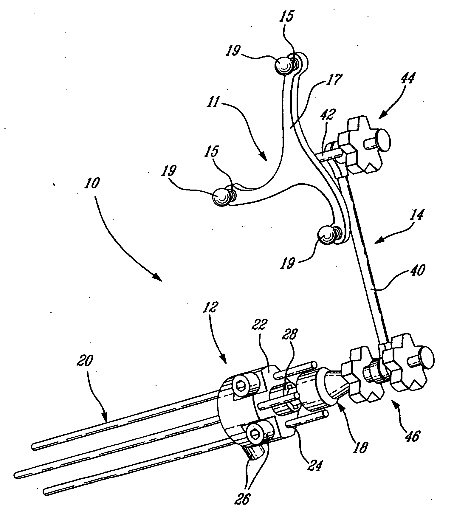
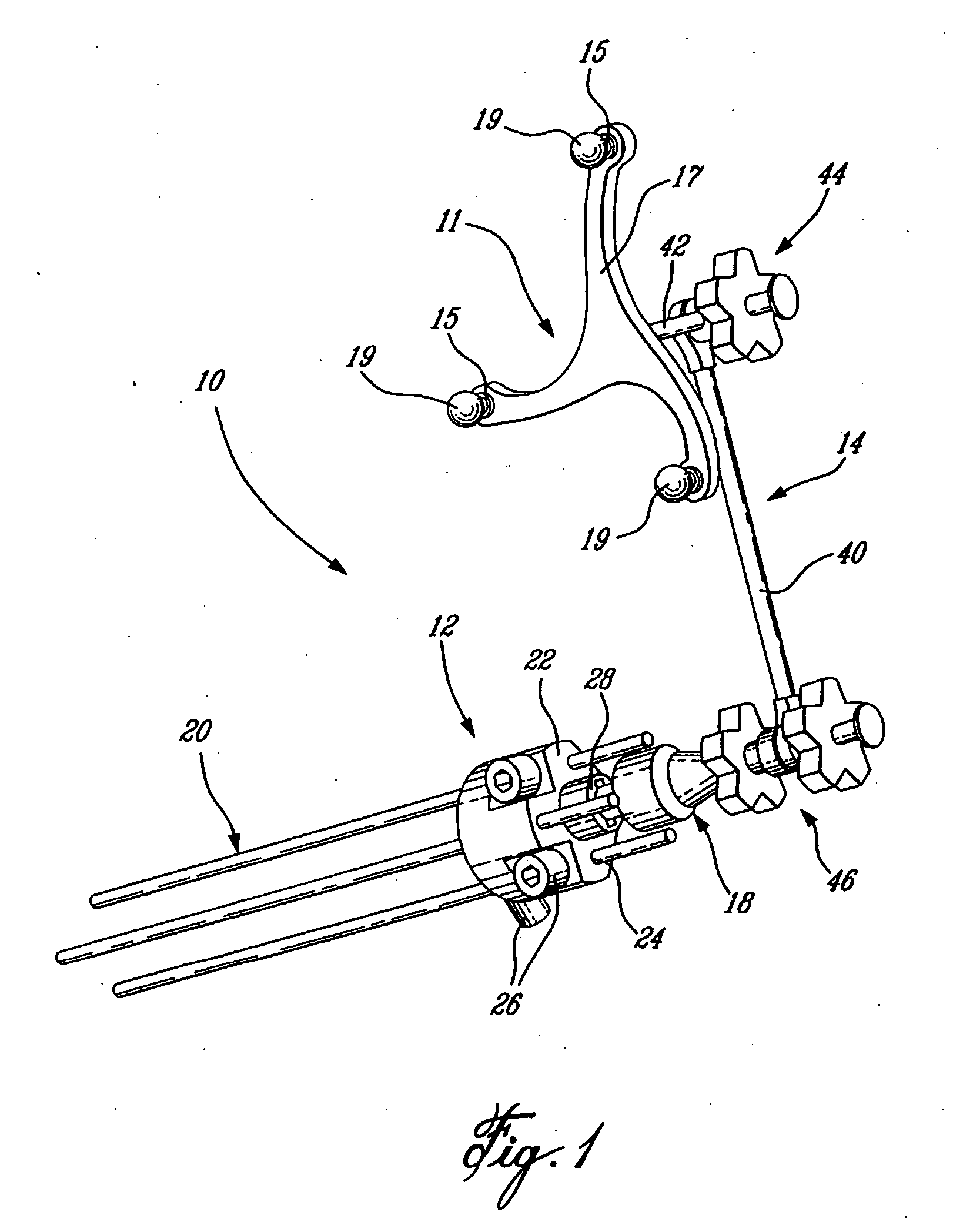
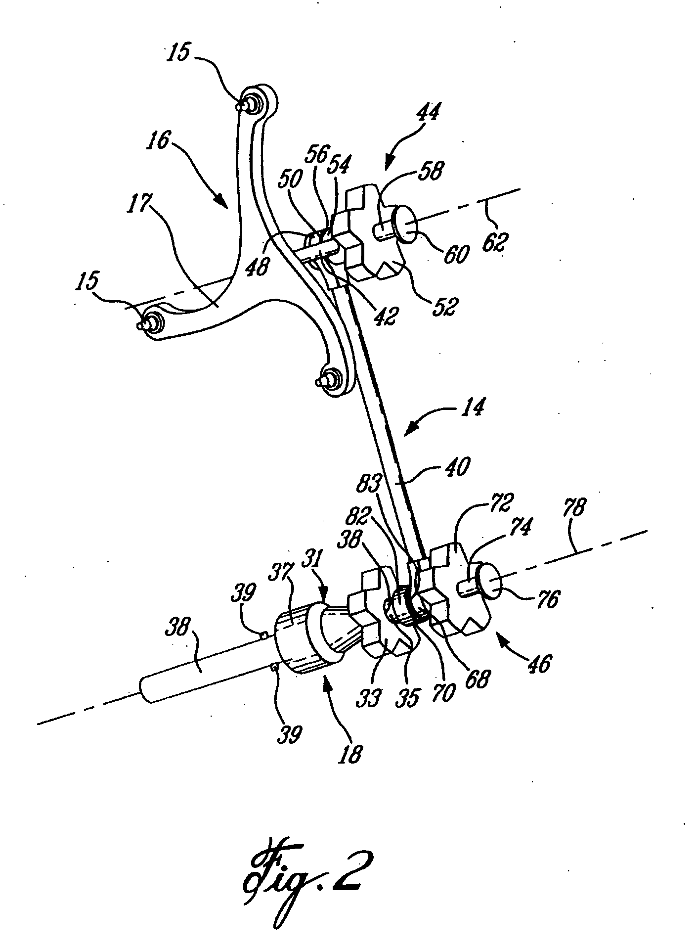
[0027] Referring to FIG. 1, a surgical bone reference assembly 10 generally comprises a bone anchor member 12, an articulated tracker support 14, having a trackable member 16 engaged at one end thereof, and being removably engageable and disengageable with the bone anchor member 12 by an attachment member 18. The trackable member 16 is adapted to be communicable with a computer assisted surgery (CAS) system capable of detecting and tracking the device in three-dimensional space within a surgical field. As best seen in FIG. 3, the bone anchor member 12 comprises preferably a cylindrical body 22 having at least one pin hole 24 extending axially therethrough for receiving at least one bone mounting pin 20 (FIG. 1). Preferably, however, three bone mounting pins 20 are used to fasten the bone anchor block 12 to a bone element of a patient such that no movement of the bone anchor member 12 relative to the bone element is possible. Three pin holes 24 are accordingly provided in the cylindr...


PUM


Abstract

A surgical bone reference assembly for communication with a CAS system, comprises a bone anchor fastenable to a bone element, an adjustable support and a trackable member that is located and tracked in three dimensional space by the CAS system. The support is removably fastenable to the bone anchor member and permits variable positioning relative to the bone anchor member. The support is intra-operatively detachable from and re-fastenable to the bone anchor member. A method of using a CT-free CAS system for determining a change in position of an un-tracked target limb is also provided. The method comprises engaging the trackable bone reference member to another bone element, locating and digitizing a landmark on the target limb, digitizing the landmark again following joint reduction, and determining at least one of a post-joint reduction limb length discrepancy and a target limb medio-lateral offset.

Description

CROSS-REFERENCE TO RELATED APPLICATIONS [0001] This is a continuation of International Application No. PCT / CA2004 / 000159 filed Feb. 4, 2004, designating the United States, which itself claims priority on U.S. provisional application 60 / 404,758 and 60 / 444,691 which were respectively filed Apr. 30, 2003 and Feb. 4, 2003, the specifications of all of which are incorporated herein by reference.TECHNICAL FIELD [0002] The present invention relates generally to a trackable reference for use in conjunction with a Computer Assisted Surgery (CAS) system. BACKGROUND OF THE INVENTION [0003] CAS systems capable of real time location and tracking of a plurality of CAS identifiable markers in a surgical field are desirable. A variety of systems are now employed, some of which require that the necessary bone elements of the patient be identified and registered to pre-operatively taken anatomical scans or intra-operatively taken images of the same bone elements. In order for the relevant bone elemen...

Claims


Application Information

Patent Timeline
IPC IPC(8): A61B5/00A61B17/00A61B19/00
CPCA61B19/26A61B19/5244A61B19/54A61B2017/00477A61B2019/5483A61B2019/5255A61B2019/5268A61B2019/5272A61B2019/5416A61B2019/505A61B34/20A61B90/39A61B90/50A61B2034/105A61B2034/2055A61B2034/2068A61B2034/2072A61B2090/3916A61B2090/3983
Inventor JUTRAS, SEBASTIENJANSEN, HERBERT ANDRECHOUINARD, BENOITYUN, ANDREW G.FONTAINE, ISABELLE
Owner ORTHOSOFT
Why Eureka
Try Eureka