Method and apparatus for generating a vibrational stimulus

Active Publication Date: 2006-01-19
ENG ACOUSTICS
View PDF13 Cites 58 Cited by
  • Summary
  • Abstract
  • Description
  • Claims
  • Application Information

AI Technical Summary

Benefits of technology

[0022] A further object or feature of the present invention is a new and improved transducer that can easily be located against the body when installed under or on a garment, or on the seat or back of a cha

Problems solved by technology

When implemented as small, wearable devices, these transducers produce only a low level vibrational output, making them difficult to be perceived by a user who is not concentrating on trying to detect the sensation.
They also, in general, provide a diffuse type sensation, so that the exact location of the stimulus on the body may be difficult to discern; as such, they might be adequate to provide a simple alert such as to indicate an incoming call on a cellular phone, but would not be adequate to provide spatial information by means of the user detecting variable stimuli from various sites on the body.
Typically these devices operate at a single frequency, and cannot be optimized for operating over the frequency range where the skin of the human body is most sensitive to vibrational stimuli.
Rotating devices have a particular problem with start up, since they have to rotate up to speed, so there is a delay between activating the device and the vibrational output.
Piezoelectric designs have also been used for vibrotactile transducers, but in general provide very small displacements, resulting in low vibration output unless the device is very large.
Other piezoceramic approaches have used benders to impart a lateral motion against the skin, but they tend to be easily damped when in contact with the skin, thus reducing their motion and consequently, their detectability.
While these devices can provide high levels of sensation, they do not meet

Method used


Image

  • Method and apparatus for generating a vibrational stimulus
  • Method and apparatus for generating a vibrational stimulus
  • Method and apparatus for generating a vibrational stimulus

Examples


Embodiment Construction

[0045] Referring to FIGS. 1 through 13, wherein like reference numerals refer to like components in the various views, there is illustrated therein a new and improved vibrotactile transducer apparatus, generally denominated 10 herein.

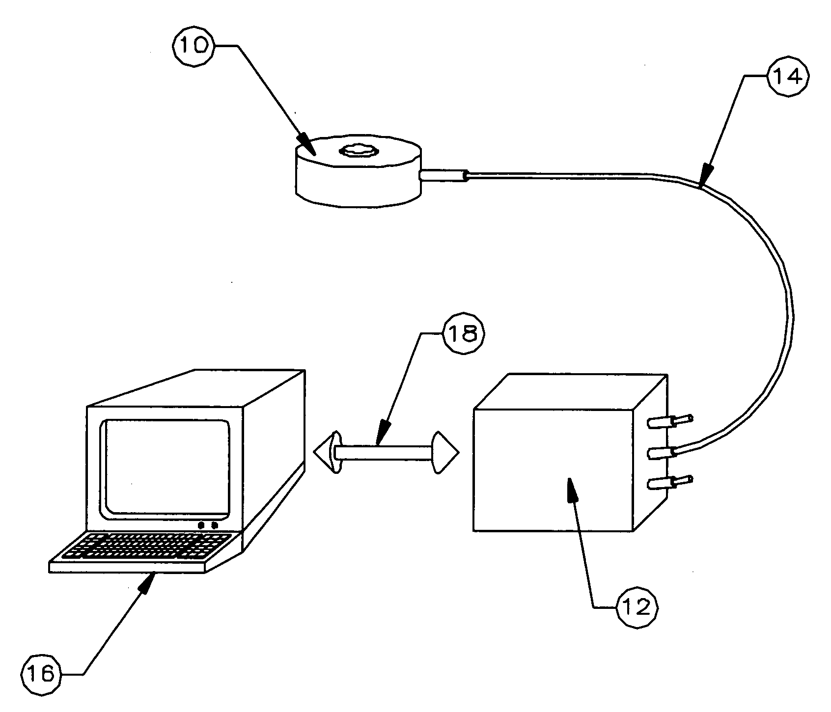
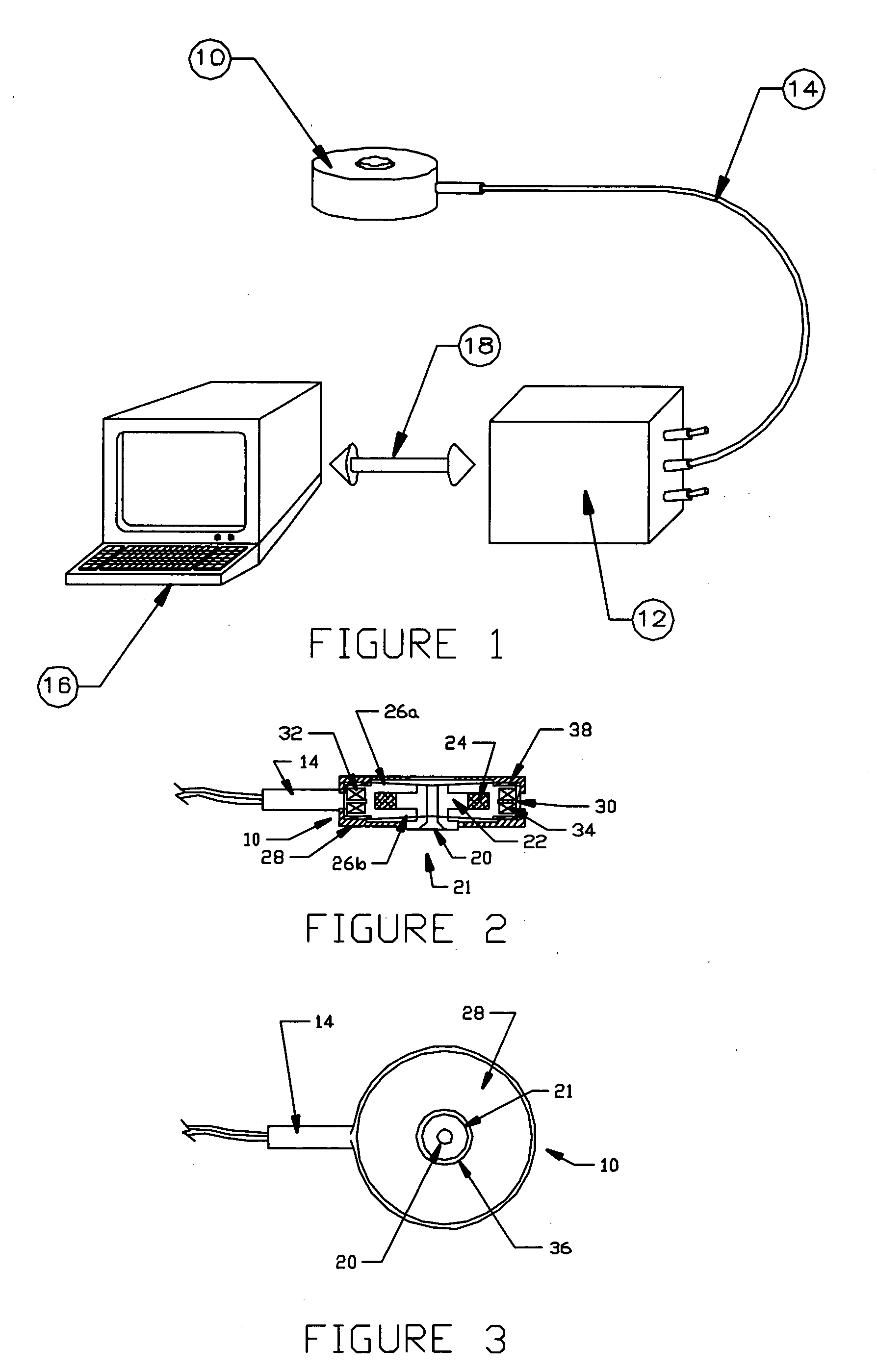
[0046]FIG. 1 illustrates a first preferred embodiment of the vibrotactile transducer of this invention. A lightweight, physically compact and electrically efficient tactile transducer is herein described that could elicit a localized sensation on the skin. FIG. 1 is an isometric view of a vibrotactile transducer 10 with its associated controller and driver electronics. One or more transducer(s) 10 are connected to controller / driver electronics 12 by connecting cable 14. A computer or other controller 16, for example a portable digital assistant (PDA) may communicate with controller / driver 12 via either a digital bus, analog control lines or wireless interface 18. The driver / external power source may contain a signal synthesizer and linear or switching ...


PUM


Abstract

A vibrotactile transducer provides a point-like vibrational stimulus to the body of a user in response to an electrical input. The apparatus includes a housing held in contact with the skin and a moving mechanical contactor protruding through in an opening in said housing and preloaded into skin. The contactor is attached to a torroidal moving magnet assembly suspended by springs in a magnetic circuit assembly consisting of a housing containing a pair of electrical coils. The mass of the magnet/contactor assembly and the compliance of the spring are chosen so that the electromechanical resonance of the motional masses, when loaded by a typical skin site on the human body, are in a frequency band where the human body is most sensitive to vibrational stimuli. By varying the drive signal to the vibrotactile transducer and activating one or more transducer at specific location on the body using an appropriate choice of signal characteristics and/or modulation, different information can be provided to a user in a intuitive, body referenced manner.

Description

[0001] This application is a continuation-in-part of U.S. Utility patent application Ser. No. 10 / 290,759, filed Nov. 8, 2002.CROSS REFERENCE TO RELATED APPLICATIONS [0002] Not applicable. STATEMENT REGARDING FEDERALLY SPONSORED RESEARCH OR DEVELOPMENT [0003] Not applicable. REFERENCE TO A MICROFICHE APPENDIX [0004] Not applicable. TECHNICAL FIELD [0005] The present invention relates generally to vibrators, transducers, and associated apparatus, and more specifically to an improved method and apparatus for generating a vibrational stimulus to the body of a user in response to an electrical input. BACKGROUND INFORMATION / DISCUSSION OF RELATED ART INCLUDING INFORMATION DISCLOSED UNDER 37 CFR 1.97 AND 37 CFR 1.98 [0006] The sense of feel is not typically used as a man-machine communication channel, however, it is as acute and in some instances as important as the senses of sight and sound, and can be intuitively interpreted (e.g., think of one's response to being tapped on the shoulder)....

Claims


Application Information

Patent Timeline
IPC IPC(8): A61H1/00
CPCA61H23/0218A61H2201/5005A61H2201/5007
Inventor ZETS, GARY A.ENSIGN, THOMAS H.CHAPMAN, FRANK D.MORTIMER, BRUCE J.P.
Owner ENG ACOUSTICS
Why Eureka
Try Eureka