Apparatus for generating an enhanced vibrational stimulus using a rotating mass motor

a technology of rotating mass and vibrational stimulus, which is applied in the field of vibrational stimulus generators and transducers, can solve the problems of not being able to provide information to users through vibrational stimulus, cannot be implemented as a wearable device, and the motor housing movement is three-dimensional and complex, and achieves low cost, low cost, and maximizes the effect of actuator displacemen

Active Publication Date: 2016-10-25
MORTIMER BRUCE J P +2
View PDF17 Cites 20 Cited by
  • Summary
  • Abstract
  • Description
  • Claims
  • Application Information

AI Technical Summary

Benefits of technology

[0020]The present invention provides a novel implementation of a low cost eccentric mass motor vibrotactile transducer. Preferably the eccentric mass and motor form part of the transducer actuator moving mass (mechanical contactor). The actuator moving mass is in contact with a skin (body) load. The actuator moving mass is constrained into approximately vertical motion (perpendicular to the skin (body) surface) by a spring between the actuator housing and moving mass. The rotational forces provided by an eccentric mass (EM) motor are therefore constrained into predominantly one dimensional motion that actuates perpendicularly against a skin (body) load. The actuator housing contacting face is in simultaneous contact with the skin (body) load. The body load, actuator moving mass, spring compliance and housing mass make up a moving mass resonant system. The spring compliance and system component masses can be chosen to maximize the actuator displacement while minimizing the housing motion, and tailor the transducer response to a desired level. This configuration can be implemented as a low mass wearable vibrotactile transducer or as a transducer that is mounted within a soft material such as a seat. A particular advantage of this configuration is that the moving mass motion can be made almost independent of force loading on the transducer housing.
[0021]The method and apparatus for generating a vibrational stimulus of this invention provides an improved small, low cost vibrotactile transducer to provide a strong tactile stimulus that can be easily felt and localized by a user involved in various activities, for example flying an aircraft, playing a video game, or performing an industrial work task. Due to the high amplitude and point-like sensation of the vibrational output, the inventive vibrotactile transducer (“tactor”) can be felt and localized at various positions on the body, and can provide information to the user. The transducer itself is a small package that can easily be located against the body when installed under or on a garment, or on the seat or back of a chair. The drive electronics are compact, able to be driven by batteries, and follows conventional motor driver control techniques. The overall transducer may include interface circuitry that is compatible with digital (e.g., TTL, CMOS, or similar) drive signals typical of those from external interfaces available from computers, video game consoles, and the like.

Problems solved by technology

Although this device does have the potential to measure a human subject's reaction to vibratory stimulus on the skin (body), and control the velocity, displacement and extension of the tappet by measurement of acceleration, the device was developed for laboratory experiments and was not intended to provide information to a user by means of vibrational stimuli nor be implemented as a wearable device.
A common shortcoming of these previous design approaches is that the transducers are rapidly damped when operated against the body—this is usually due to the mass loading of the skin (body) or the transducer mounting arrangement (for example the foam material that would surround a vibrotactile transducer if it were mounted in a seat).
Thus the resultant motion of the motor housing is three dimensional and complex.
However, there are practical limits to this as the force imparted to the bearing increases with rotational velocity and the motor windings are designed to support a maximum current.
It should also be apparent that the angular momentum and therefore the eccentric motor vibrational output also increases with rotational velocity which limits use of the device over bandwidth.
This is somewhat longer than the skin (body)'s temporal resolution, thus can limit data rates.
If the vibrotactile feedback is combined with other sensory feedback such as visual or audio, the start-up delay has the potential of introducing disorientation.
Secondly, from the conservation of momentum, if the mass loading on the motor is changed, the torque on the motor and angular rotation rate will also change.
In fact it is not possible to simultaneously and independently control output vibration level and frequency.
This is obviously undesirable from a control standpoint, and in the limiting case, a highly loaded transducer would produce minimal displacement output and thus be ineffective as a tactile stimulus.
This is obviously undesirable from a control standpoint, and in the limit, a highly loaded transducer would also produce minimal displacement output and thus be ineffective as a tactile stimulus.
This approach relies on a complex mechanical linkage that is both expensive to implement and at high rotational velocities prone to deleterious effects of friction.
In summary, EM motors when used as vibrotactile transducers, provide a mounting dependent vibration stimulus and a diffuse type sensation, so that the exact location of the stimulus on the body may be difficult to discern; as such, they might be adequate to provide a simple alert such as to indicate an incoming call on a cellular phone, but would not be adequate to reliably provide spatial information by means of the user detecting stimuli from various sites on the body.
The prior art fails to recognize the design requirements to achieve a small, wearable vibrotactile device that provides strong, efficient vibration performance (displacement, frequency, force) when mounted against the skin (body) load of a human.
Further, the effect of damping on the transducer vibratory output due to the additional mechanical impedance coupled to the mounting has not been adequately addressed.
The prior art further fails to effectively utilize an eccentric mass motor as the force generator in vibrotactile transducers or provide methods that extend the high frequency bandwidth and control the response of the transducer.

Method used


Image

  • Apparatus for generating an enhanced vibrational stimulus using a rotating mass motor
  • Apparatus for generating an enhanced vibrational stimulus using a rotating mass motor
  • Apparatus for generating an enhanced vibrational stimulus using a rotating mass motor

Examples


Embodiment Construction

[0053]Referring to FIGS. 1 through 17B, wherein like reference numerals refer to like components in the various views, there is illustrated therein a new and improved vibrotactile transducer apparatus.

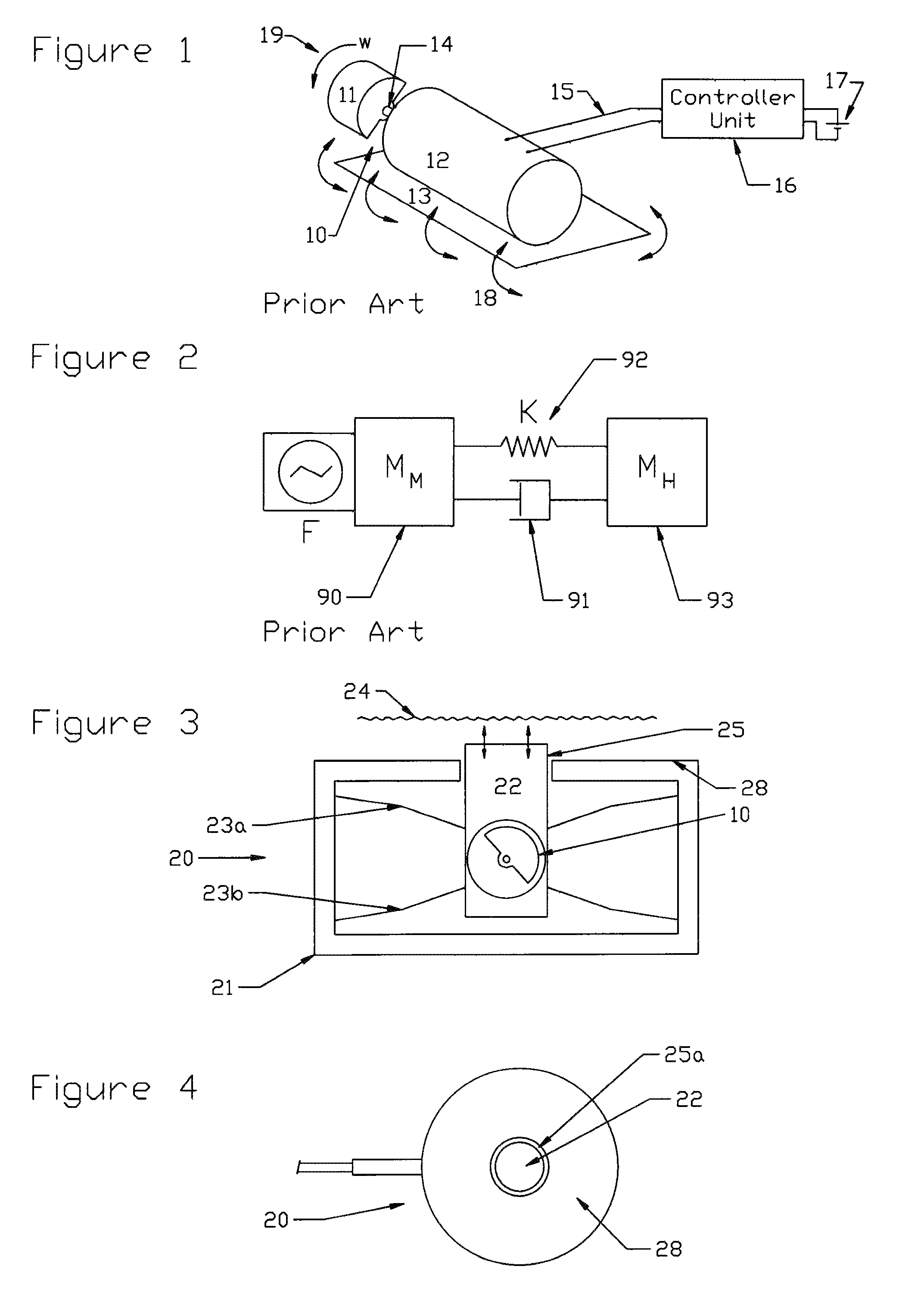
[0054]FIG. 1 illustrates the operation of prior art eccentric mass (EM) motor or pager motors 10. An eccentric mass 11 is mounted on a shaft 14 driven by a motor 12 that is mounted on a base 13. The motor is usually a DC motor although various synchronous, stepper, variable reluctance, ultrasonic and AC motors can be used. The motor 12 is connected to a controller unit 16 by wires 15. The controller unit is powered with a battery or power supply 17. The eccentric mass 11 is usually half-circular cylinder or similar shape where the center of mass is not the same as the center of rotation. The center of rotation is determined by the motor's shaft 14. The motor is designed to rotate the shaft 14 and off-center mass load 11 at various rotational velocities 19. From the conservation of angu...


PUM


Abstract

A low cost eccentric mass motor vibrotactile transducer provides a point-like vibrational stimulus to the body of a user in response to an electrical input. Preferably the eccentric mass and motor form part of the transducer actuator moving mass. The actuator moving mass is constrained into vertical motion by a spring between the actuator housing and moving mass. The actuator moving mass is in contact with a skin (body) load. The actuator housing is in simultaneous contact with the body load. The mass of the motor/contactor assembly, mass and area of the housing, and the compliance of the spring are chosen so that the electromechanical resonance of the motional masses, when loaded by the typical mechanical impedance of the skin (body), are in a frequency band where the human body is most sensitive to vibrational stimuli 150-300 Hz.

Description

CROSS REFERENCE TO RELATED APPLICATIONS[0001]The present application is a continuation-in-part of application Ser. No. 11 / 787,275, filed Apr. 16, 2007, and now issued as U.S. Pat. No. 8,398,569, issued Mar. 19, 2013, and which claimed the benefit of the filing date of U.S. Provisional Patent Application Ser. No. 60 / 792,248, filed Apr. 14, 2006. The foregoing applications are incorporated by reference in their entirety as if fully set forth herein.STATEMENT REGARDING FEDERALLY SPONSORED RESEARCH OR DEVELOPMENT[0002]Not applicable.REFERENCE TO A MICROFICHE APPENDIX[0003]Not applicable.TECHNICAL FIELD[0004]The present invention relates generally to vibrators, transducers, and associated apparatus, and more specifically to an improved method and apparatus for generating a vibrational stimulus to the body of a user in response to an electrical input.BACKGROUND INFORMATION AND DISCUSSION OF RELATED ART[0005]The sense of feel is not typically used as a man-machine communication channel, ho...

Claims


Application Information

Patent Timeline
Patent Type & Authority Patents(United States)
IPC IPC(8): A61H23/02
CPCA61H23/0263A61H2201/0138A61H2201/0149A61H2201/0165A61H2201/149A61H2201/165A61H2201/1664A61H2201/50A61H2201/5002A61H2201/5005A61H2201/5064A61H2230/655
Inventor MORTIMER, BRUCE J. P.ZETS, GARY A.STICKLER, SCOTT
Owner MORTIMER BRUCE J P
Why Eureka
Try Eureka