Actuator alarm for critical environments or applications

a technology for actuators and environments, applied in the direction of thermometers, measuring devices, instruments, etc., can solve the problems of system wide failure of the cellular telephone system, significant economic or safety repercussions, and inability to protect the operation of the actuator and the actuator

Inactive Publication Date: 2006-01-26
NAT ENVIRONMENTAL PRODS
View PDF1 Cites 29 Cited by
  • Summary
  • Abstract
  • Description
  • Claims
  • Application Information

AI Technical Summary

Benefits of technology

[0009] It is a further object of the present invention to provide an actuator system which disables the alarm when the motor and the coupled air damper or valve reaches an operational end point (the physical limit of the air damper or valve).

Problems solved by technology

Therefore, potential failures of these actuators are typically not critical and the installation of these actuators and the operation of the actuators are typically not protected or fall within the scope of recommended periodic maintenance contracts and building maintenance procedures.
However, some applications which utilize of air damper actuators or valve actuators are critical in that the failure of the actuator (to open or close upon command) can create significant economic or safety repercussions.
For example, when an actuator is used in an unmanned cellular telephone transfer station which is remote and moderately inaccessible during winter time (or during other adverse weather conditions), the failure of the actuator may result in a system wide failure of the cellular telephone system.
A failure of the actuator in these unmanned cellular telephone transfer stations may deprive thousand of customers of cellular telephone service for prolonged periods of time.
Therefore, the cellular service provider is both economically at risk and its reputation for high quality “always ON” cellular telephone service may be affected.
If the actuator fails to open or close the damper or valve (due to damper / valve failure), dire consequences may result.
Actuator failure usually results due to a failure of the air damper or valve or a “locking up” of the damper or valve rather than the actuator failing to operate.
Since the actuator motors are coupled, either directly or via a gear system, to mechanically movable air dampers or valves, the air dampers or valves may become sticky and difficult to move or motivate over time.
Although less likely, hydraulic valves are subject to similar deteriorating operating conditions.
Further, the grease or lubricant utilized in and on air dampers or valves may become sticky or less lubricous and the mechanical damper or valve may generate resisting torque contrary to the movement of the actuator motor.
Also, the air damper and valve may oxidate (rust) over time and such oxidation further restricts the movement of the air damper or valve.

Method used


Image

  • Actuator alarm for critical environments or applications
  • Actuator alarm for critical environments or applications
  • Actuator alarm for critical environments or applications

Examples


Embodiment Construction

[0019] The present invention relates to an air damper or valve actuator system with an alarm feature and a distributed system for monitoring a plurality of such actuator systems and methods for detecting and issuing alarms indicative of potential impending mechanical failure of the air damper or valve actuator systems.

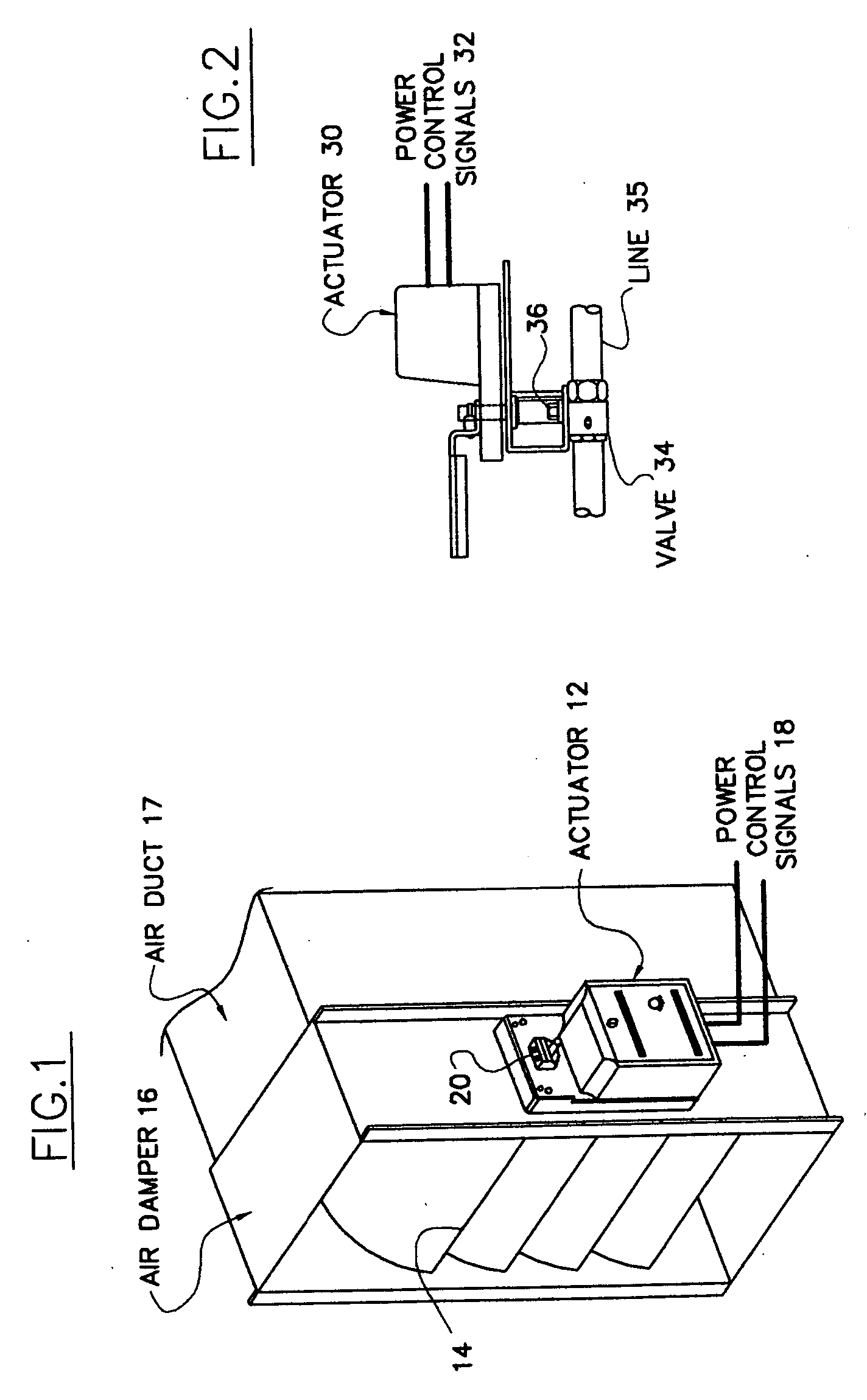
[0020]FIG. 1 diagrammatically illustrates air damper actuator 12 (which includes a motor, not shown) coupled via coupling 20 to a mechanical linkage system (not shown) permitting vanes 14 to move and open and close the air duct 17. The vanes dampen air flow through the duct. Air damper 16 is known by persons of ordinary skill in the art. Actuator 12 receives power control signals 18 from a command and control system usually located somewhere in the facility which houses the entire ventilation system, of which duct 17 is a part thereof.

[0021]FIG. 2 diagrammatically illustrates valve actuator 30 receiving power control signals 32. Actuator 30 is mechanically coupled vi...


PUM

PropertyMeasurementUnit
electrical poweraaaaaaaaaa
electricalaaaaaaaaaa
currentaaaaaaaaaa

Abstract

The air damper or valve actuator system with an alarm includes a motor coupled to the air damper or valve, an electrical power sensor for sensing an electrical power characteristic of the motor during the motor's motive operation of the air damper or valve and a threshold sensor. The threshold sensor determines and generates an alarm signal when the power characteristic exceeds a predetermined value during the motor's motive operation. An end point sensor is utilized to detect when the motor and coupled air damper or valve reaches a mechanical operational end point thereby disabling the alarm. The method for detecting and issuing an alarm indicative of potential impending mechanical failure includes sensing the product characteristic and determining and generating an alarm when the power characteristic exceeds a predetermined value before the motor driven actuator reaches a pre-set mechanical end position. The distributed system which monitors a plurality of actuator systems via a central control station.

Description

[0001] The present invention relates to an air damper or valve actuator system with an alarm feature and a distributed system for monitoring a plurality of such actuator systems and methods for detecting and issuing an alarm indicative of potential impending mechanical failure of the air damper or valve systems. BACKGROUND OF THE INVENTION [0002] Actuators are utilized to open and close air dampers in heat, air conditioning and ventilation systems (HVAC systems) and are also used to open and close valves in hydraulic systems. These actuators customarily include motors and controllers which respond to control signals applied thereto by external master HVAC or hydraulic control centers. In most situations, air damper actuators (which control air flow through HVAC ventilation systems) and valve actuators (which control hydraulic flow through pipes and tubes) are installed and located in places which are easy to reach by installers and subsequent maintenance personnel. Therefore, potent...

Claims


Application Information

Patent Timeline
Patent Type & Authority Applications(United States)
IPC IPC(8): G01K13/00
CPCG01K13/00
Inventor KOPEL, ZEV
Owner NAT ENVIRONMENTAL PRODS
Why Eureka
Try Eureka