Overflow downdraw glass forming method and apparatus

a glass forming and downdrawing technology, applied in the field of glass sheet manufacturing, can solve the problems of limited control of process temperature and flow, glass defects, and limitations of the apparatus, and achieve the effects of reducing the effect of thermal creep on the thickness variation of the glass sheet, reducing the effect of thermal creep, and modifying the “overflow process”

Active Publication Date: 2006-01-26
CORNING INC
View PDF37 Cites 104 Cited by
  • Summary
  • Abstract
  • Description
  • Claims
  • Application Information

AI Technical Summary

Benefits of technology

[0015] The present invention significantly modifies “The Overflow Process”. It includes a method and apparatus for measuring glass flow rate and maintaining a constant glass flow rate. It also embodies design features and methods that support and stress the forming apparatus in a manner such that the deformation that results from thermal creep is corrected, thus minimizing the effect of the thermal creep on the thickness variation of the glass sheet. The present invention also embodies design features that change the process from a single step (combined flow distribution and cooling) to a two step process; step one being flow distribution and step two being cooling.

Problems solved by technology

The teachings of U.S. Pat. No. 3,338,696 are still the state of the art as practiced today; however, the apparatus has limitations.
A drawback of the apparatus of “The Overflow Process” is that, even though it makes excellent glass during stable operating conditions, the control of process temperature and flow is limited by simplistic control technology, thus allowing unintended process transients which cause glass defects.
Defects caused by the flow and temperature transients eventually subside when the process stabilizes; however, there is a period of time where the quality of the glass sheet is substandard.
Another drawback of the apparatus of “The Overflow Process” is that the forming apparatus deforms during a manufacturing campaign in a manner such that the glass sheet no longer meets the thickness specification.
This is a primary cause for premature termination of the production run.
Another drawback of the apparatus of “The Overflow Process” is that the production rate of the present forming apparatus design is limited by the use of a single step process to both distribute the glass and cool the glass prior to drawing the sheet.
The limited production rate makes the cost of the glass sheet that is produced less competitive in the market.

Method used


Image

  • Overflow downdraw glass forming method and apparatus
  • Overflow downdraw glass forming method and apparatus
  • Overflow downdraw glass forming method and apparatus

Examples


Embodiment Construction

[0065] The present invention provides technology for measurement of glass flow rate as it enters the forming apparatus of the sheet manufacturing process and discloses a procedure for regulating this process flow. As presently practiced in the prior art, the measurement of glass flow rate is determined by the quantity of the product produced at the end of the production line. The present invention incorporates energy balance information and preferably uses representative measurements of the glass stream temperature as outlined in U.S. Pat. No. 6,895,782 and patent application Ser. No. 11 / 011,657, as contrasted with prior art measurements of the temperature of the outer surface of the process piping.

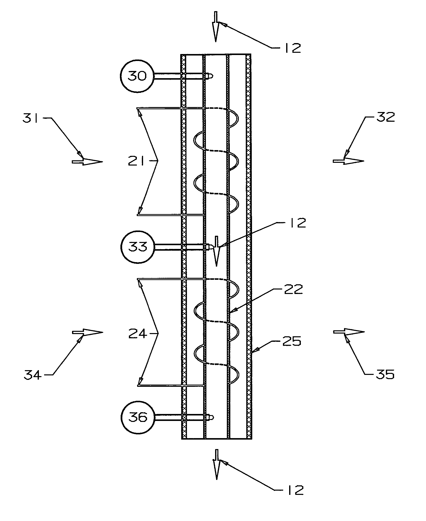
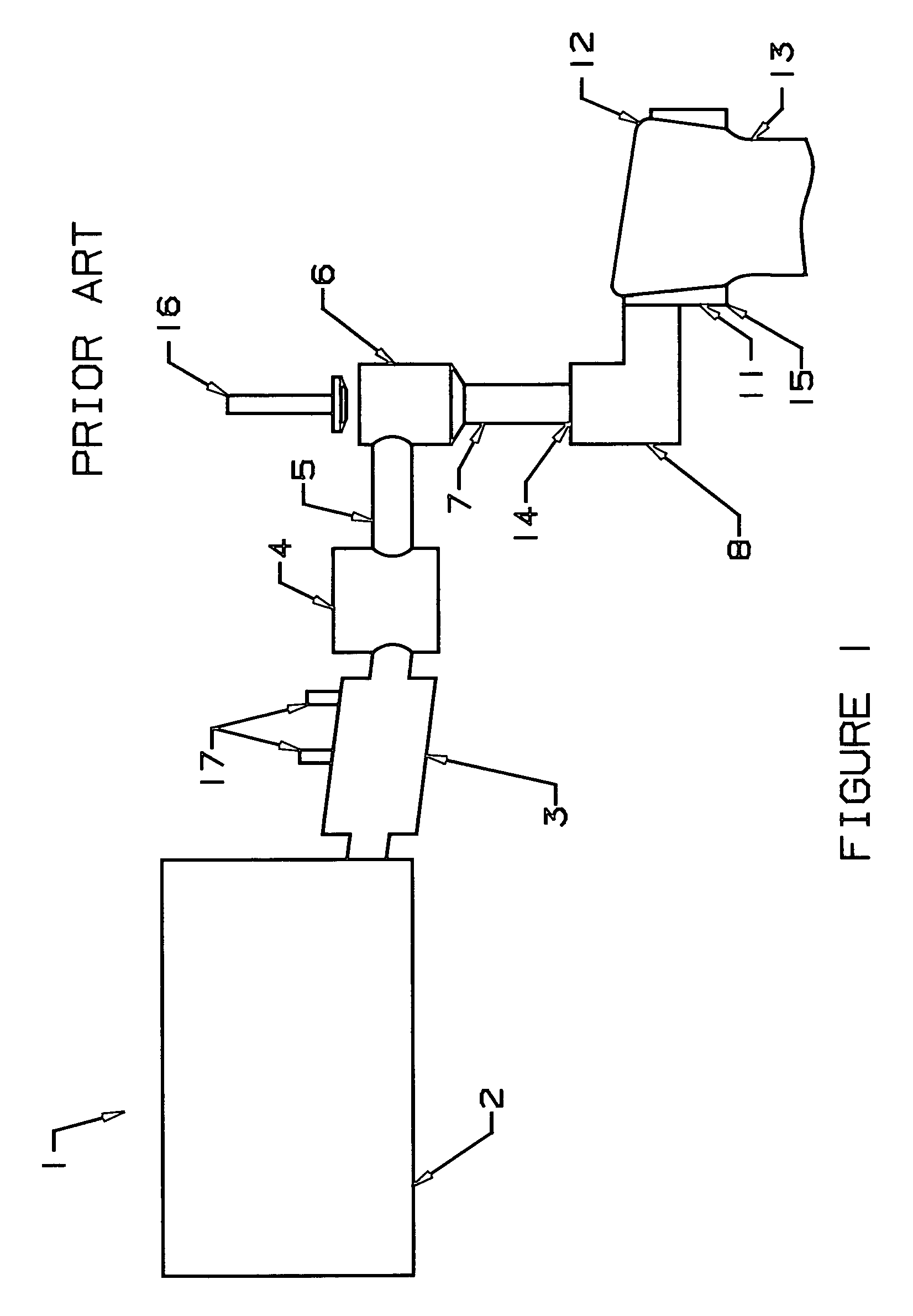
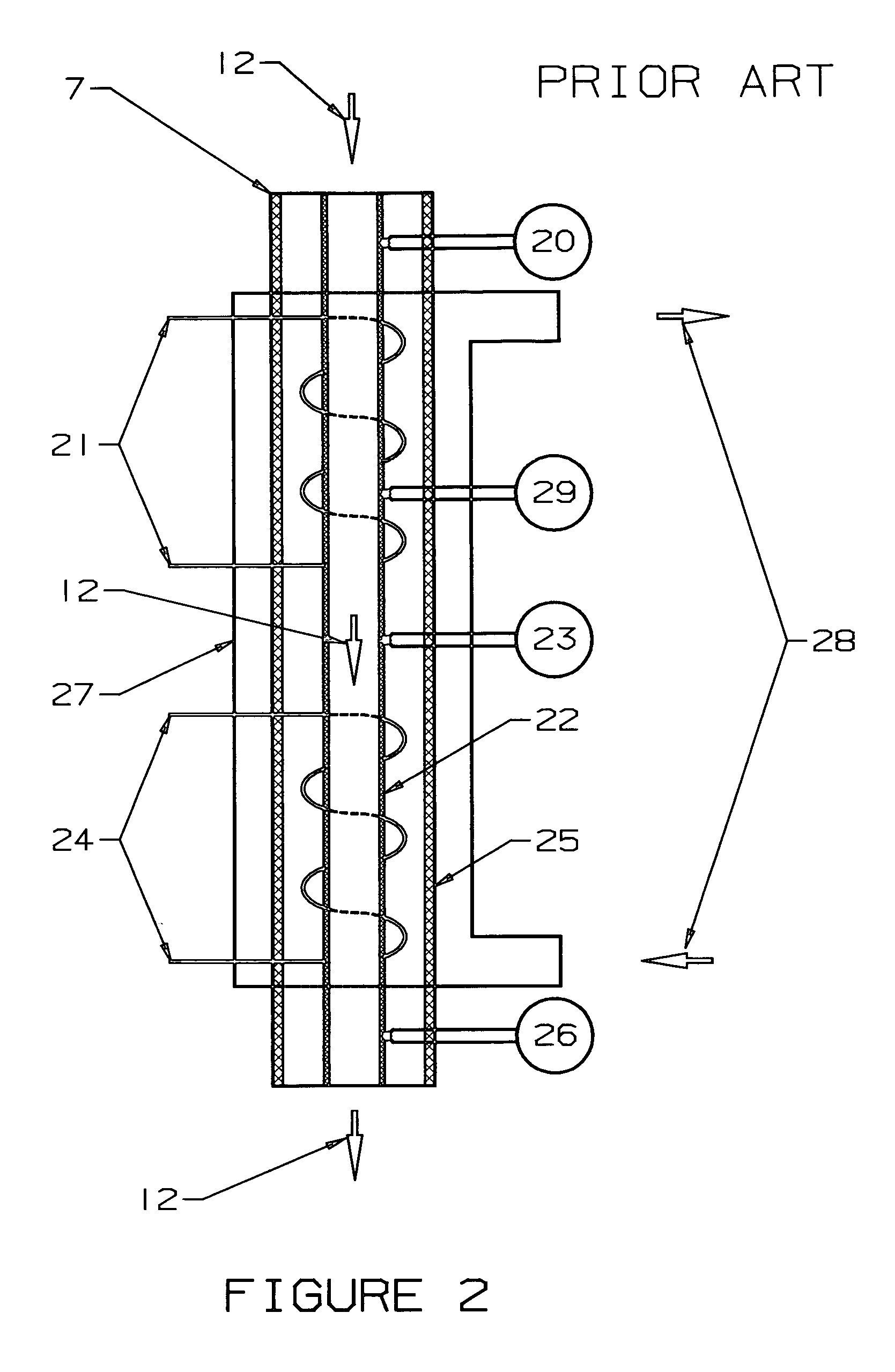
[0066] The glass “Sheet Forming Apparatus” normally designed for use in “The Overflow Process” (U.S. Pat. No. 3,338,696) relies on a specifically shaped forming block to distribute the glass in a manner to form sheet of a uniform thickness. The basic shape of this forming block is descri...


PUM

PropertyMeasurementUnit
temperaturesaaaaaaaaaa
viscosityaaaaaaaaaa

Abstract

The present invention significantly modifies “The Overflow Process”. It includes a method and apparatus for measuring glass flow rate and maintaining a constant glass flow rate. It also embodies design features and methods that support and stress the forming apparatus in a manner such that the deformation that results from thermal creep is corrected, thus minimizing the effect of the thermal creep on the thickness variation of the glass sheet. The present invention also embodies design features that change the process from a single step (combined flow distribution and cooling) to a two step process; step one being flow distribution and step two being cooling.

Description

REFERENCE TO RELATED APPLICATIONS [0001] This application claims an invention, which was disclosed in the following Provisional Applications: [0002] 1) Provisional Application No. 60 / 589,535, filed Jul. 20, 2004, entitled “GLASS FLOW RATE CONTROL FOR SHEET GLASS FORMING APPARATUS”; [0003] 2) Provisional Application No. 60 / 655,077, filed Feb. 22, 2005, entitled “SHEET GLASS FORMING APPARATUS”; [0004] 3) Provisional Application No. 60 / 659,533, filed Mar. 8, 2005, entitled “METHOD AND APPARATUS FOR OVERFLOW DOWNDRAW PROCESS GLASS SHEET THICKNESS CONTROL”; and [0005] 4) Provisional Application No. 60 / 662,661, filed Mar. 17, 2005, entitled “METHOD AND APPARATUS FOR OVERFLOW DOWNDRAW PROCESS”. [0006] The benefit under 35 USC §119(e) of the United States provisional applications is hereby claimed, and the aforementioned applications are hereby incorporated herein by reference.BACKGROUND OF THE INVENTION [0007] 1. Field of the Invention [0008] The invention pertains generally to the manufac...

Claims


Application Information

Patent Timeline
Patent Type & Authority Applications(United States)
IPC IPC(8): G12B1/00C03B17/06
CPCC03B17/064G05D7/0635G01F1/6888C03B17/067
Inventor PITBLADDO, RICHARD B.
Owner CORNING INC
Why Eureka
Try Eureka