
Apparatus for detecting vibrations in a machine tool

a technology of detecting vibrations and machine tools, which is applied in the direction of machine tool testing, electrical/magnetic measuring arrangements, measuring/indication equipment, etc., can solve the problems of not presenting an adequate sensitivity to vibrations caused, the vibration coming from the tool is not transmitted correctly, and the machining of the groove between the two teeth of the gear is particularly problematic. , to achieve the effect of not worsening the detection

Inactive Publication Date: 2006-01-26
BALANCE SYST
View PDF10 Cites 4 Cited by
  • Summary
  • Abstract
  • Description
  • Claims
  • Application Information

AI Technical Summary

Benefits of technology

[0018] Not the least important aim of the invention is to provide an apparatus that will enable a balancing device to be added to the tool without worsening detection by the sensor of the vibrations sought.

Problems solved by technology

In this case, machining of the groove present between two teeth of a gear is particularly problematical.
In fact, sensors, even ones built according to very advanced technical solutions, at times do not present an adequate sensitivity to the vibrations caused by the contact of the tool with the rotating workpiece.
A fundamental cause of the above drawbacks is represented by the fact that very often the vibrations coming from the tool are not transmitted correctly to the sensors, which hence perceive to a greater extent the spurious vibrations coming from areas close to the sensor itself.
The situation is further worsened by the presence, often in an area strictly adjacent to the sensor, of balancers or equalizers, i.e., devices designed to eliminate in short times any eccentricity of the tools.
The presence of said balancers dampens considerably the vibrations transmitted to the sensor, which is thus no longer able to guarantee an adequate finish of the workpiece.
A possible solution could be to attempt to reduce the problem by calibrating the sensors so as to obtain a very high sensitivity thereof, but by doing so there may also occur cases of erroneous detection due to the vibrations caused by the mechanical members and to the noises generated by the electromagnetic emissions resulting from actuation of the mechanical parts in relative motion, said emissions being moreover present also within the body of the sensor itself.
There consequently remains unsolved the technical problem of how to obtain an apparatus for detecting vibrations which presents adequate sensitivity and response times and which does not result in erroneous detection.

Method used


Image

  • Apparatus for detecting vibrations in a machine tool
  • Apparatus for detecting vibrations in a machine tool
  • Apparatus for detecting vibrations in a machine tool

Examples


Embodiment Construction

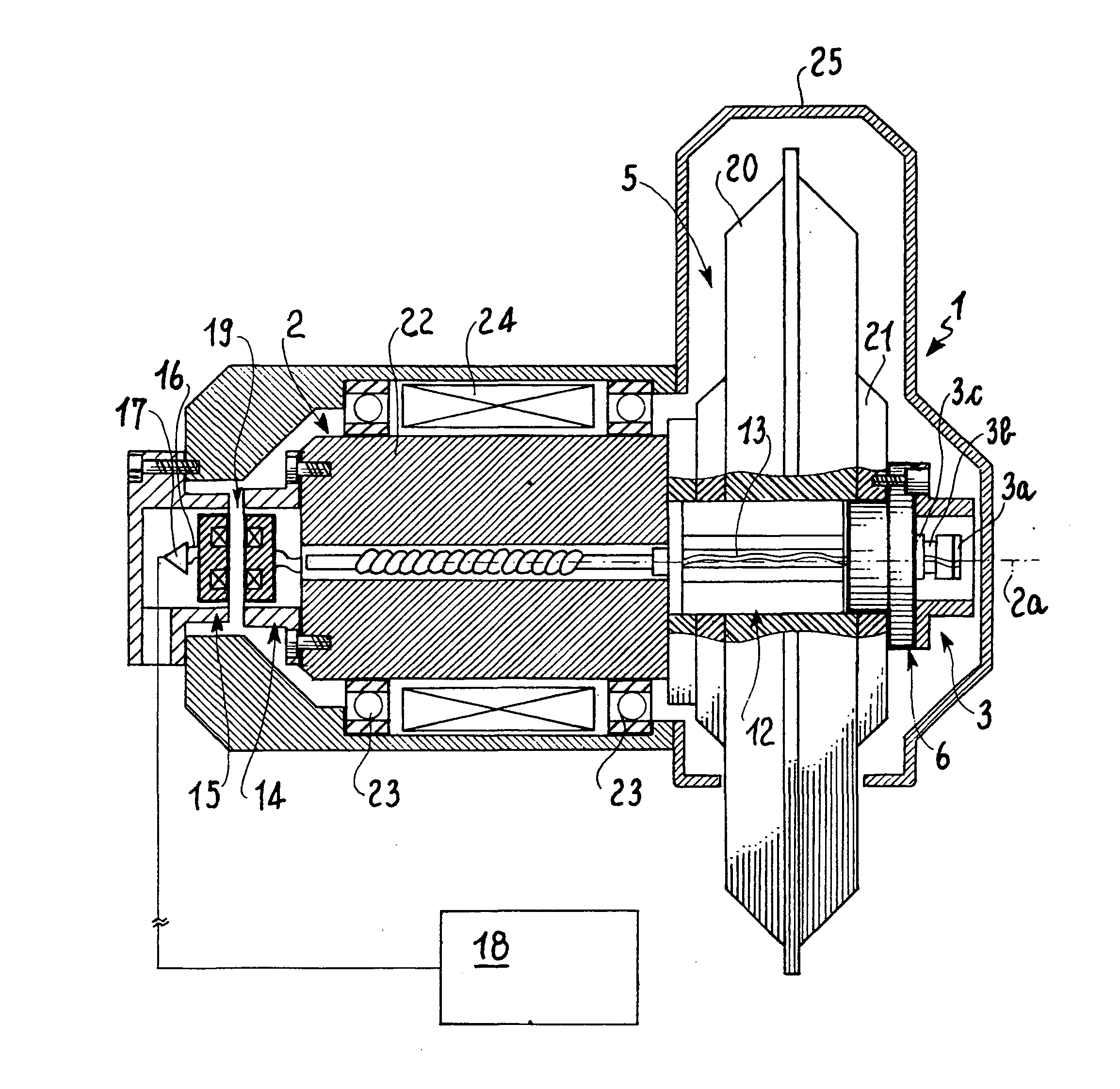
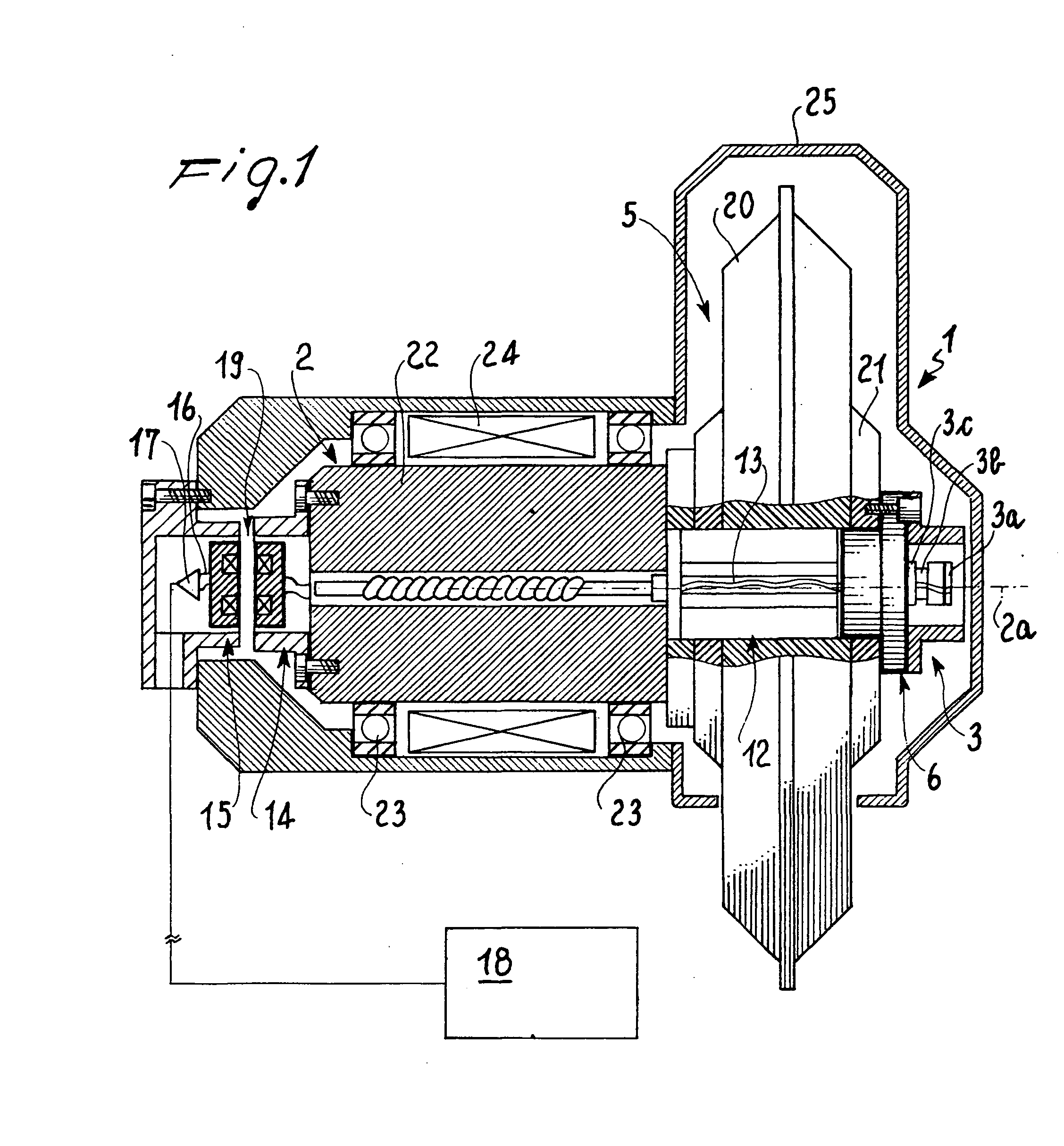
[0032] With reference to the above Figures, the apparatus according to the invention is designated as a whole by the reference number 1.

[0033] It comprises a sensor assembly 3, designed to sense the vibrations and to transmit them in the form of correlated electrical impulses.

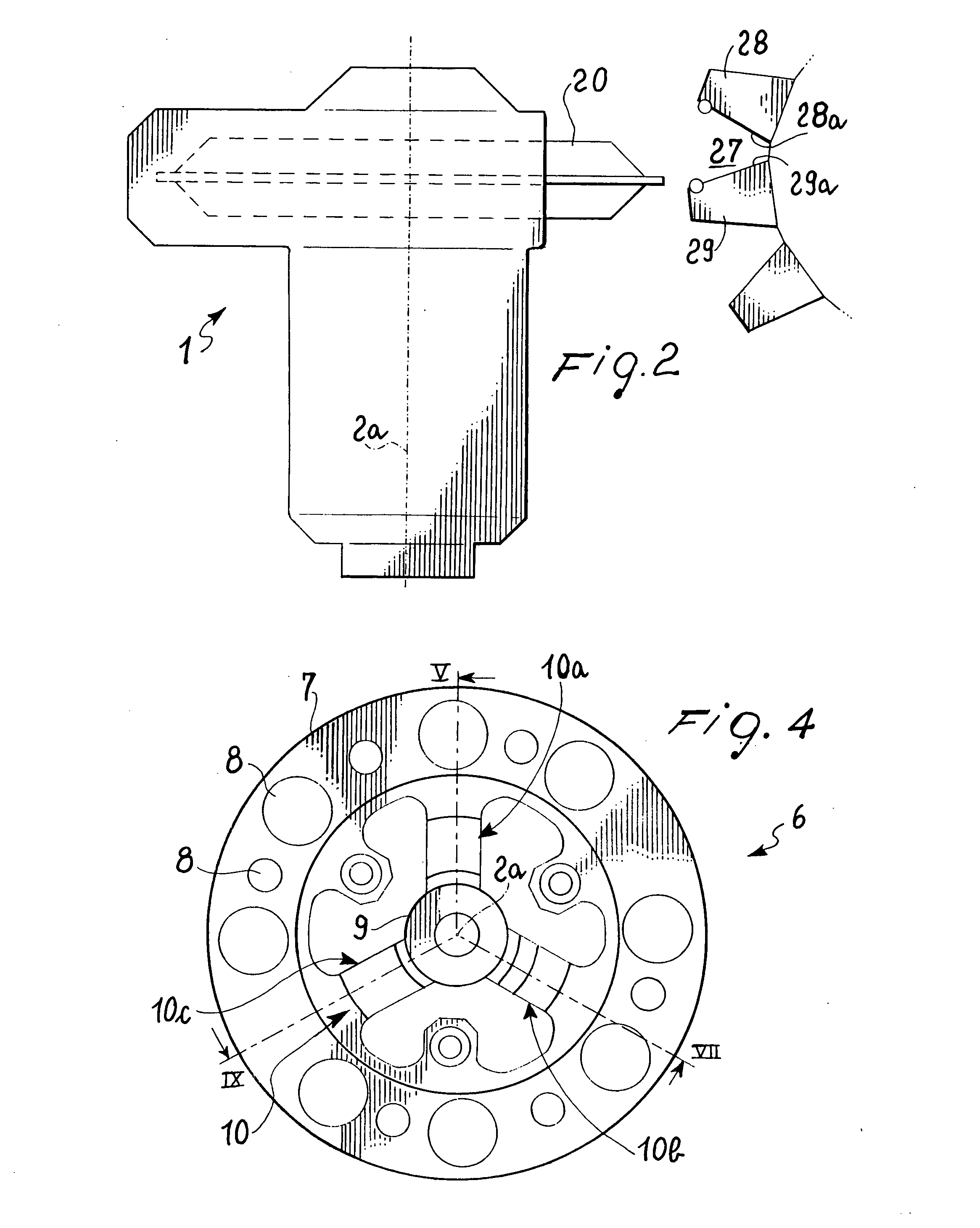
[0034] Said apparatus 1 is included in a machine tool 4, comprising a rotating rotor portion 2, which defines an axis of rotation 2a and includes tool members 5. The sensor assembly 3 is fixed to the rotor portion 2 by means of a supporting and amplification device 6 for amplifying the vibrations coming from the tool members 5.

[0035] The device 6 structurally presents a rotational asymmetry, about the axis of rotation 2a, for any angle smaller than a full circle.

[0036] An object is defined as being provided with rotational asymmetry for a given angle if it is possible to distinguish that a rotation thereof has occurred through the given angle.

[0037] Any object is symmetrical for rotations through 360°, i.e...


PUM

PropertyMeasurementUnit
frequencyaaaaaaaaaa
frequencyaaaaaaaaaa
widthaaaaaaaaaa

Abstract

Provided herein is an apparatus for detecting vibrations in a machine tool having a rotor portion (2) which is provided with tool members (5) and defines an axis of rotation (2a), the apparatus comprising a sensor assembly (3) which is able to rotate together with the rotor portion (2) and is designed to issue signals correlated to the vibrations, and a supporting and amplification device (6) for supporting the sensor assembly (3) and for amplifying the vibrations, which is set between the sensor assembly (3) and the rotor portion (2) and has a rotational asymmetry about the axis of rotation (2a) for any angle smaller than a full circle

Description

FIELD OF THE INVENTION [0001] The subject of the present invention is an apparatus for detecting vibrations in a machine tool having one rotor portion provided with tool members and defining an axis of rotation, the apparatus being of the type comprising a sensor assembly which rotates together with the said rotor portion and which is designed to issue signals correlated to the vibrations. DESCRIPTION OF THE PRIOR ART [0002] As is known, there exist machine tools including apparatuses and devices that convert the vibrations of the tools into electrical signals, by means of piezoelectric devices or the like. The electrical signal is then communicated to the control center of the machine, which can issue a command for stopping the tool or any other desired commands. [0003] Amongst said apparatuses, of major importance are the ones designed for detecting contacts between the tool and the workpiece. [0004] The above apparatuses are particularly useful because they can eliminate loadless...

Claims


Application Information

Patent Timeline
Patent Type & Authority Applications(United States)
IPC IPC(8): G01L1/00
CPCB23Q17/2404
Inventor TRIONFETTI, GIANNIGUIDOTTI, ANDREA
Owner BALANCE SYST
Learn More