Dynamic separator

a technology of dynamic separator and separator plate, which is applied in the direction of solid separation, screening, sieving, etc., can solve the problems of low efficiency of material disintegration, insufficient disintegration of movable bed in the loading part of the sieve, mixing up of disintegration fractions in the loading part, etc., to achieve low power consumption, simplify the design of the unit, and simple and reliable construction unit

Inactive Publication Date: 2006-01-26
MAININ BURKIT +3
View PDF8 Cites 5 Cited by
  • Summary
  • Abstract
  • Description
  • Claims
  • Application Information

AI Technical Summary

Benefits of technology

[0010] Technical task of the invention is to design a simple and reliable in construction unit with low power-consuming jigging process.
[0011] The separator we offer by our invention consists of two movable troughs, hinged via crankshafts. The upper trough has a sieve. The unit has flexible membrane made in the form of an endless stripe, one edge of that is achieved to the upper tough, and the other—to the lower one. Movement of toughs is achieved by torque transmission from a drive (e.g. Electric engine) to the crankshaft, and from it to the troughs. The troughs make advance movement along curved closed trajectory—circumference. Extreme and inner cranks of the crankshaft are located in respect to each other with the displacement of 180 degree, that provides the movement of troughs in counter-phase. In this case the design of the unit is simplified considerably due to absence of the usage of double-arm levers, reliability is increased thanks to removal inertia forces and energy consumption of jigging is decreased as both troughs move along closed trajectory and their masses perform only positive work. Negative effect upon the base is minimized due to full balance of moving masses of the unit.
[0012] To improve reliability durability and simplicity of the flexible membrane the latter has been done not as a continuous but as an endless stripe both edges of which are attached to the troughs.
[0013] Thus, constructive differences of this unit give possibilities to solve the technical task—decreasing power intensity, reduction design and increasing reliability of the unit. Consequently, these differences are very essential. To our mind, they give possibility to provide the proper technical level to the given invention. Industrial usage of it is out of any doubt.

Problems solved by technology

Disadvantage of the device is insufficient disintegration of the movable bed in the loading part of the sieve and mixing up of disintegrating fractions in the loading part.
Thus, the efficiency of material disintegration is low.
Due to these reasons as well as some others the type of the devices with the movable sieve did not find wide application.
Disadvantages of the machine are complexity of the design due to eccentric unit construction, high inertia of the lower part of the machine that results in high energy-consumption because of the fact that each cycle of jigging needs upraising of the lower trough with the whole amount of water, low efficiency of jigging as there is no simultaneous upraising of the whole bed that is characteristic of all jiggers with unmovable sieve.
Because of the cinematic scheme and correspondingly the design itself the disadvantages of the machine are that the troughs make reciprocal motion and as result of this the considerable part of the drive capacity is spent to overcome inertia rather than to the useful performance.
Besides it result in considerable additional loads over the drive and hinges of the machine that is negatively effects reliability of the machine.

Method used


Image

  • Dynamic separator
  • Dynamic separator

Examples


Embodiment Construction

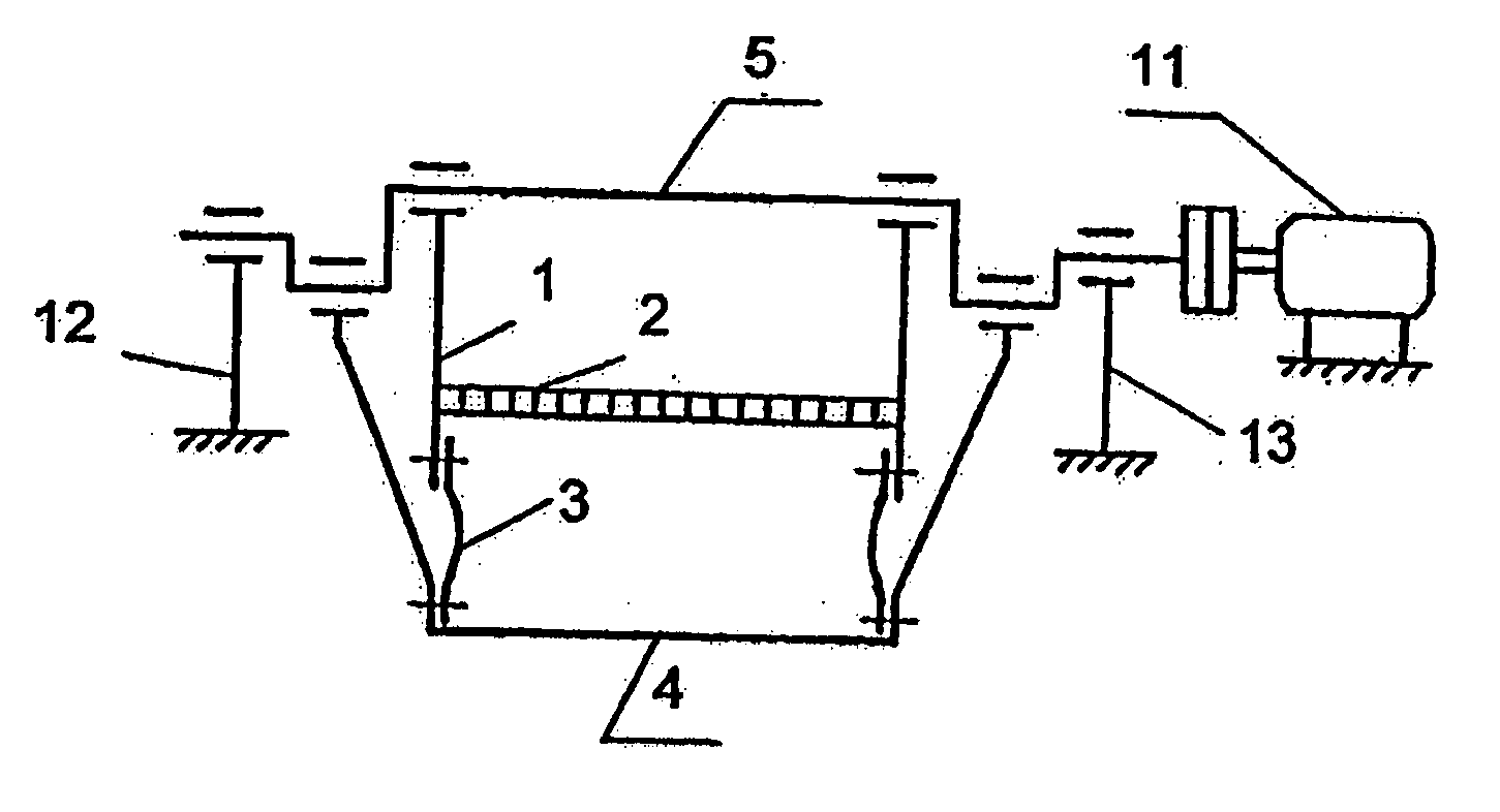
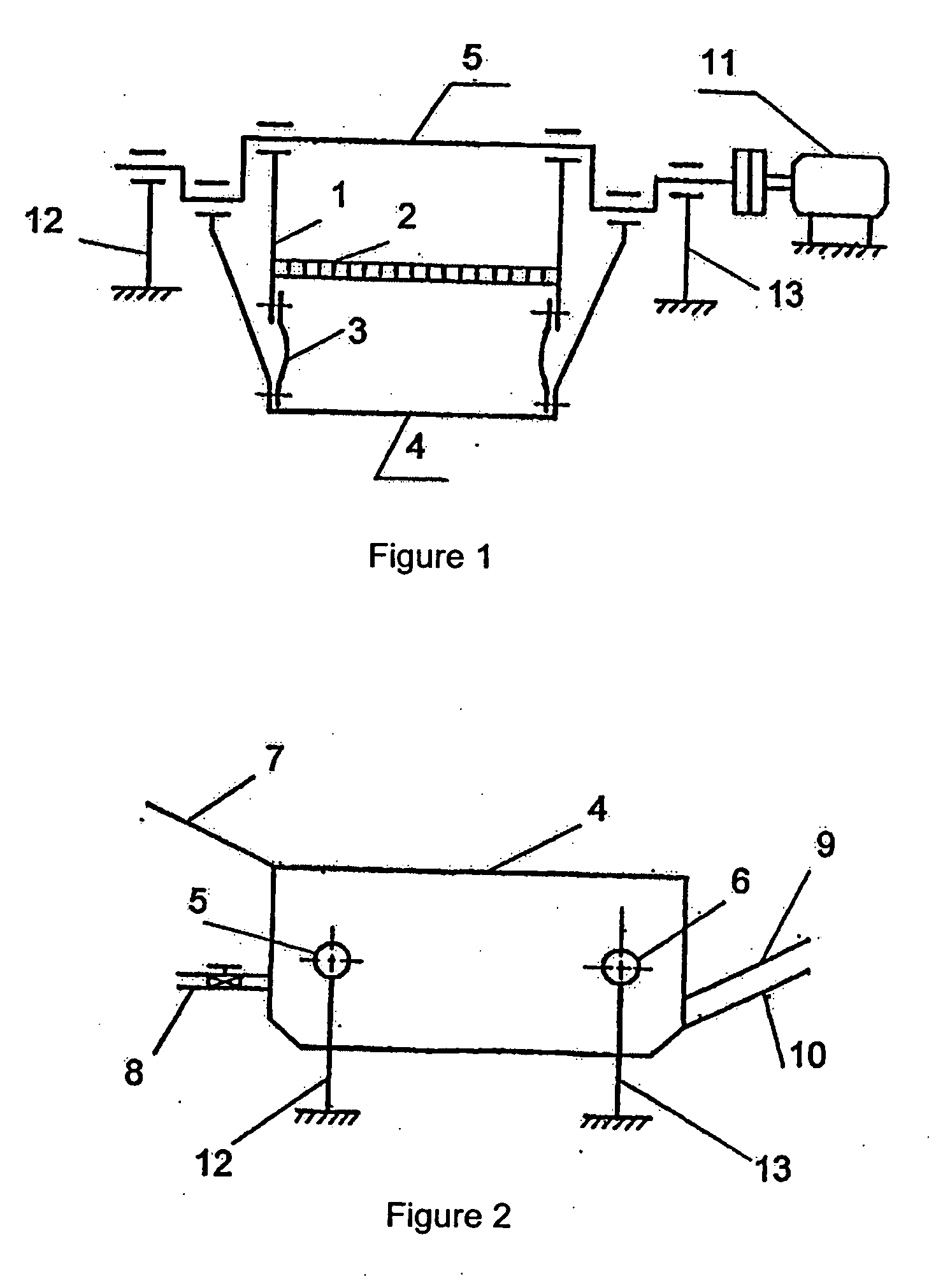
[0016] The unit consists of upper trough 1 with sieve 2 and flexible membrane 3 attached at the bottom, lower trough 4 with attached to it flexible membrane 3 and hinged to upper trough 1 with the help of crankshafts 5 and 6. At the back butt end of upper trough 1 there is a loading unit 2, water along flexible hose 8 is given to under sieve 2. Unloading processing products is done through unloading units 9 and 10 placed on front butt end of trough 1. The troughs are put into operation vie the crankshaft by drive 11. Crankshafts 5 and 6 are hinged on supports 12 and 13.

[0017] The given device operates in the following way. Material processed is given onto upper trough 1 out of loading unit 7. Drive 11 via crankshaft gives advance movement to troughs 1 and 4. Synchronously with the movement of lower trough 4 downward replacement of upper 1 with sieve 2 takes place upwards that provides uprising of the whole bed. With the movement of upper trough 1 together with sieve 2 downward lowe...


PUM


Abstract

The invention relates to mineral processing and can be used for the metal mining, coal and other industries. The inventive device comprises two movable trays which are pivotally connected to each other and actuated by a specially constructed shaft. The positive motion of the trays makes it possible to obtain a uniform pulse distribution, thereby preconditioning the stimulation of mineral processing. In addition, said invention substantially reduces energy consumption for mineral processing, simplifies the structural design of the device, and significantly increases the reliability thereof. The test of the pilot device displayed good technical results of mineral processing and confirmed the high reliability and operability of said easy producible device.

Description

CROSS-REFERENCE DATA [0001] The present patent application in an entry in national phase of the international patent application no. PCT / KZ2003 / 000005 filed Aug. 4, 2003, which claims priority of Kazakh patent application no. 2002 / 1085.1 filed Aug. 19, 2002.FIELD OF THE INVENTION [0002] This paper is dealing with processing minerals and can be used both in ore and mining industries, as well as in some others. BACKGROUND OF THE INVENTION [0003] There are certain jigging units with movable sieve (Directory on ore processing. Main processes. Moskow, Nedra, 1983, p.p. 53-54). The sieve is given bow-shaped movement with horizontal displacement towards the place of loading material with the sieve moving down and protruding it forward under moving up. As a result the positive effect is achieved due to simultaneous up going of the whole bed and pushing separating material forward along the sieve, the regulation of the sieve movement is done by replacement of the plates with cranks on the mo...

Claims


Application Information

Patent Timeline
IPC IPC(8): B07B1/42B03B5/16B03B5/18B03B5/24
CPCB03B5/16B03B5/24B03B5/18
Inventor MAININ, BURKITERMEKOVA, GULNARMAININA, ZHANATMAININA, ZHIBEK
Owner MAININ BURKIT
Why Eureka
Try Eureka