Pellet separator

Inactive Publication Date: 2006-01-26
SATAKE CORPORATION
View PDF0 Cites 60 Cited by
  • Summary
  • Abstract
  • Description
  • Claims
  • Application Information

AI Technical Summary

Benefits of technology

[0011] The backgrounds are shaped so as to curve along the parabolic trajectory of the pellets expelled from the conveyer unit in the downstream direction, so t

Problems solved by technology

However, in the conventional colored pellet remover, a resin pellet on a line of detection P is illuminated by a plurality of fluorescent lamps 121A-121E near the photodetectors 113-115, and anything with a high degree of transparency will cause diffused reflection inside the pellet when the pellet is

Method used


Image

  • Pellet separator
  • Pellet separator
  • Pellet separator

Examples


Example

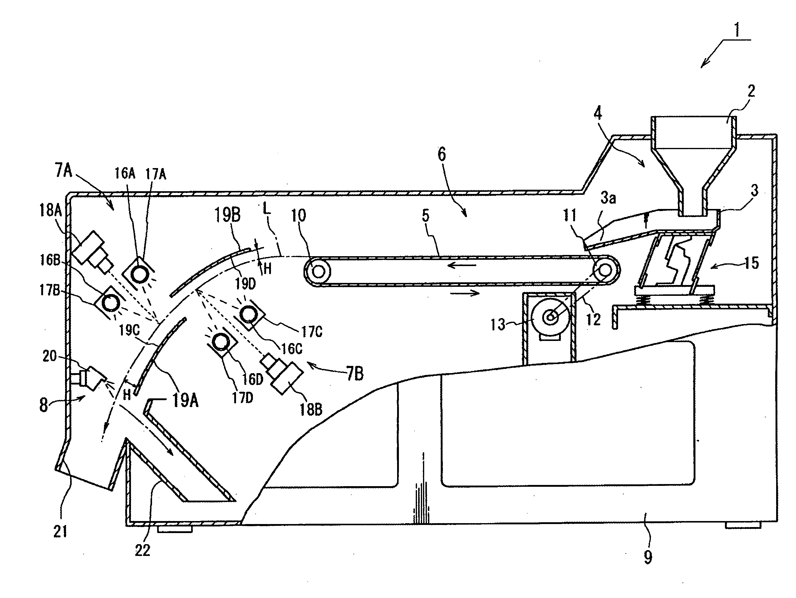
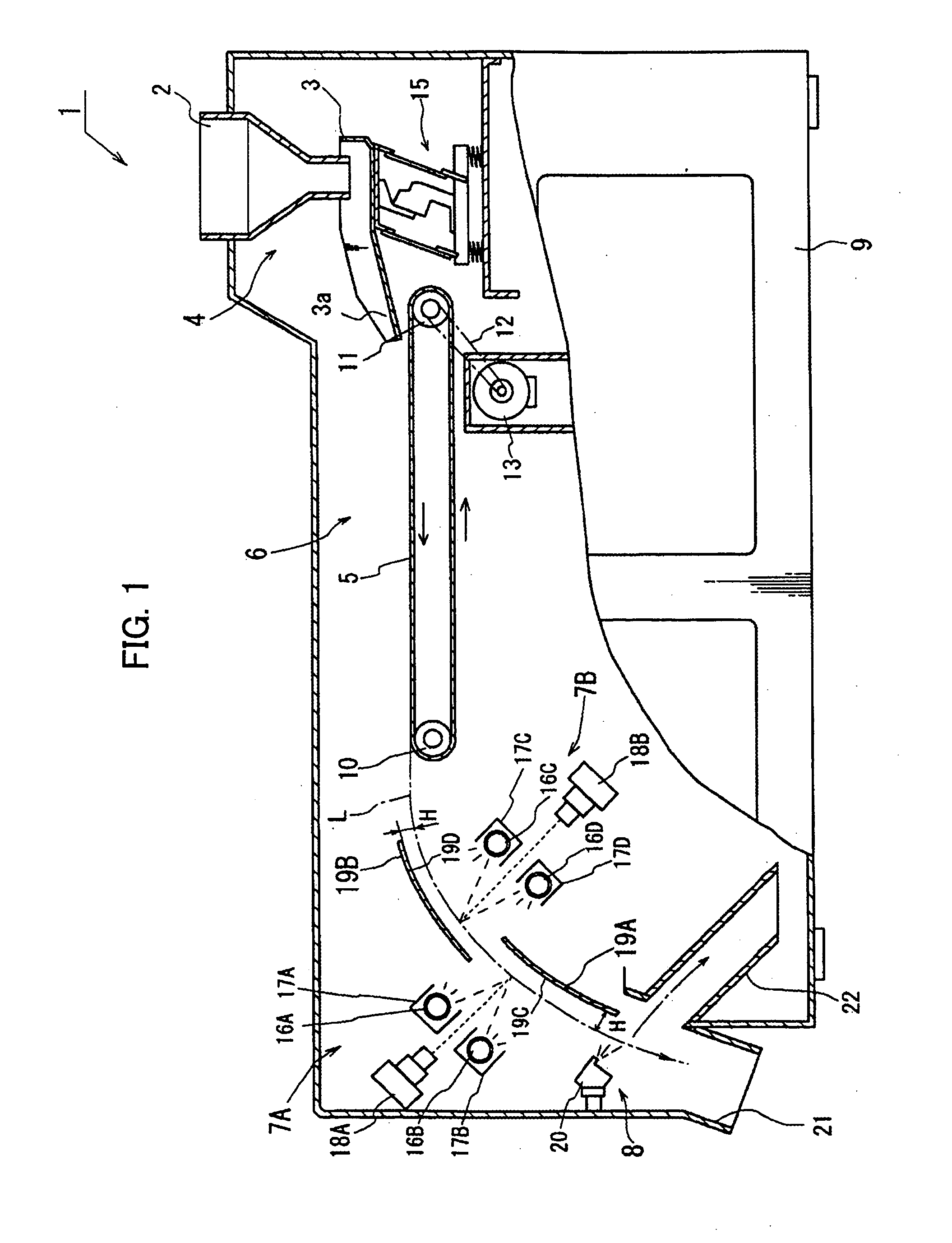
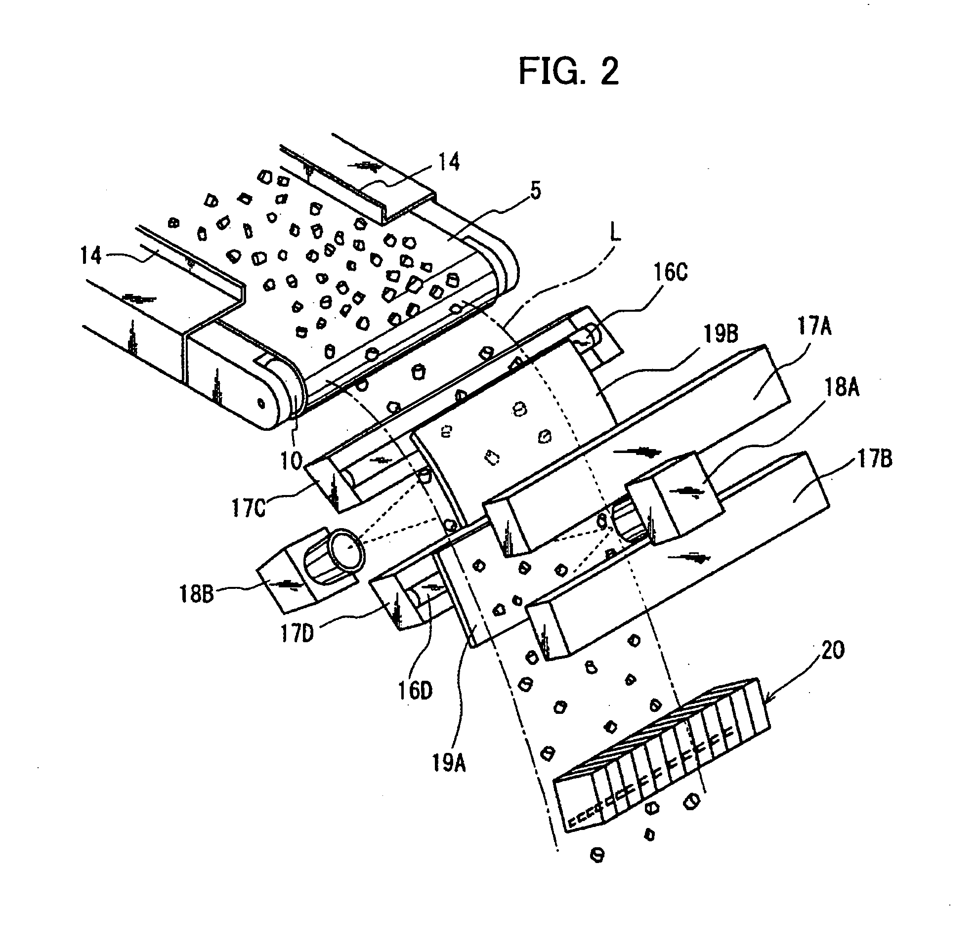
[0015] A detailed description will now be given of a preferred embodiment of the present invention, with reference to FIG. 1 and FIG. 2. FIG. 1 is a diagram showing a central longitudinal cross-sectional view of a pellet separator of the present invention, and FIG. 2 is a diagram showing a perspective view of the relation between the fall of a pellet and optical detecting units.

[0016] In FIGS. 1 and 2, a pellet separator 1 is comprised of a supply unit 2 composed of a supply hopper 3 and a supplying unit 4, a conveying unit 6 that conveys a constant volume of pellets supplied from the supplying unit 4 at a constant speed using a continuous conveyer belt 5, a plurality of optical detecting units disposed along opposite sides of a parabolic trajectory L of the pellets discharged from the conveying unit 6, and a removing unit 8 that, upon detection of a defective pellet by the plurality of optical detecting units, removes such defective pellet from the parabolic trajectory L.

[0017] T...


PUM


Abstract

A pellet separator capable of accurately sorting and removing defective pellets without generating false identifications of nondefective pellets as defective pellets by suppressing diffused reflection inside even resin pellets of high transparency. A first background and a second background of the pellet separator are formed in the vicinity of a parabolic trajectory and shaped to be curved along the parabolic trajectory in the downstream direction thereof.

Description

BACKGROUND OF THE INVENTION [0001] 1. Field of the Invention [0002] The present invention relates to a pellet separator for removing defective pellets coated with carbon or the like from translucent resin pellets and plastic pellets that are the raw material for nylon products and the like. [0003] 2. Description of Related Art [0004] To remove extremely minute amounts of colored pellets generated in a resin pellet production process, a resin pellet colored pellet remover that efficiently removes defective colored pellets is known (see JP 2651867B, for example). [0005] A detailed description will now be given of a photosensor section of this colored pellet remover using FIG. 3. FIG. 3 is a diagram showing a partial expanded view of the photosensor unit, in which photodetectors 113, 114 that detect light reflected from the front of a pellet and a photoreceptor 115 that detects light reflected from the back of the pellet are disposed on opposite sides of a drop path L, with the front p...

Claims


Application Information

Patent Timeline
IPC IPC(8): B07C5/00
CPCB07C5/366B07C5/3425
Inventor ITO, TAKAFUMITAKAYAMA, ATSUSHI
Owner SATAKE CORPORATION
Why Eureka
Try Eureka