Plasma processing apparatus

Active Publication Date: 2005-04-05
SPTS TECH LTD
View PDF19 Cites 34 Cited by
  • Summary
  • Abstract
  • Description
  • Claims
  • Application Information

AI Technical Summary

Benefits of technology

An additional independent magnetic field generator may be provided for generating a field downstream of the plasma generation chamber. The magnetic field generator and the additional magnetic field generator may be sized such that the latter has a substantially zero net effect in the plasma generation chamber. The magnetic field generator may include a first coil for generating a magnetic field in the plasma generation chamber and a second coil for converging that field at the upstream location. The first and second coils are preferably powered by a single power

Problems solved by technology

Strong variations in field strength or electron density affect the wave propagation and cause strong spatial variations in the amplitude and wave number, making it difficult to couple efficiently using a simple antenna geometry.
In the prior ar

Method used


Image

  • Plasma processing apparatus
  • Plasma processing apparatus
  • Plasma processing apparatus

Examples


Example

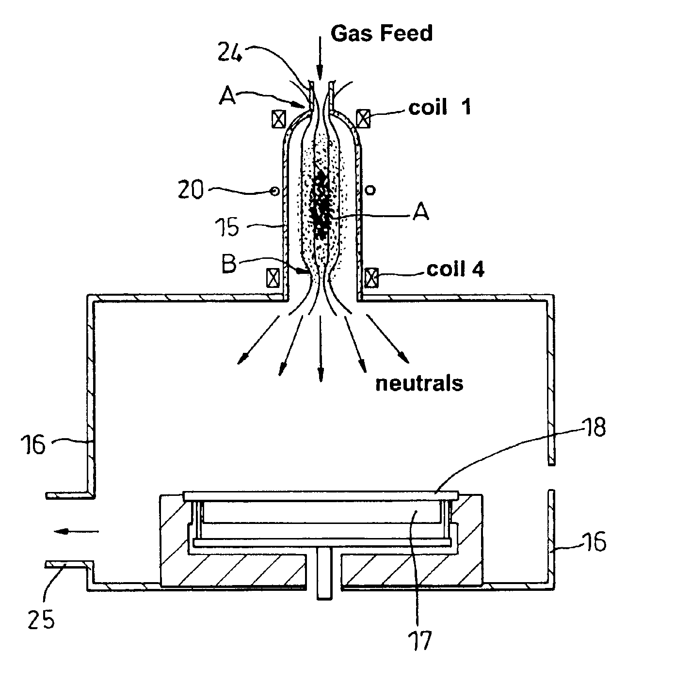
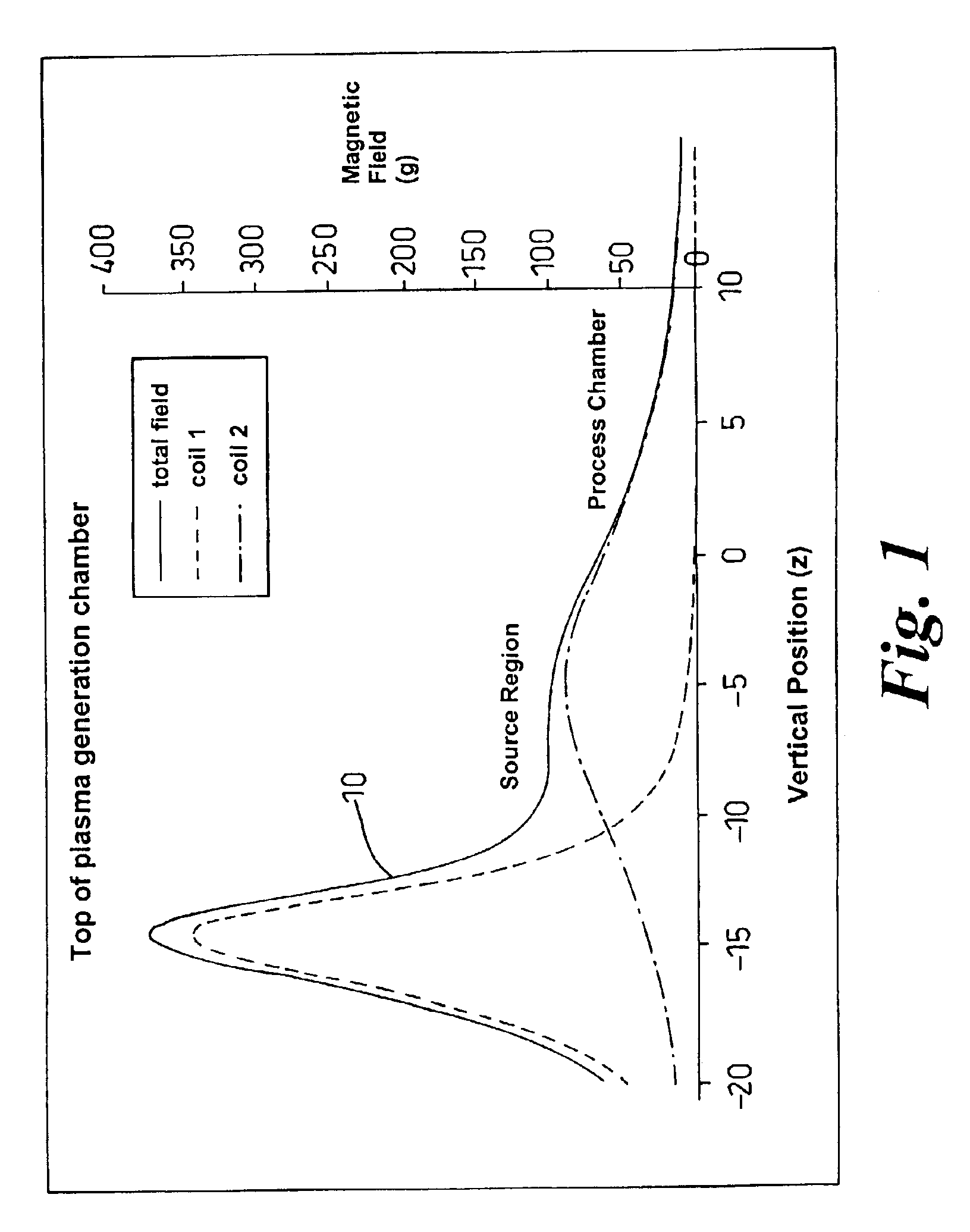
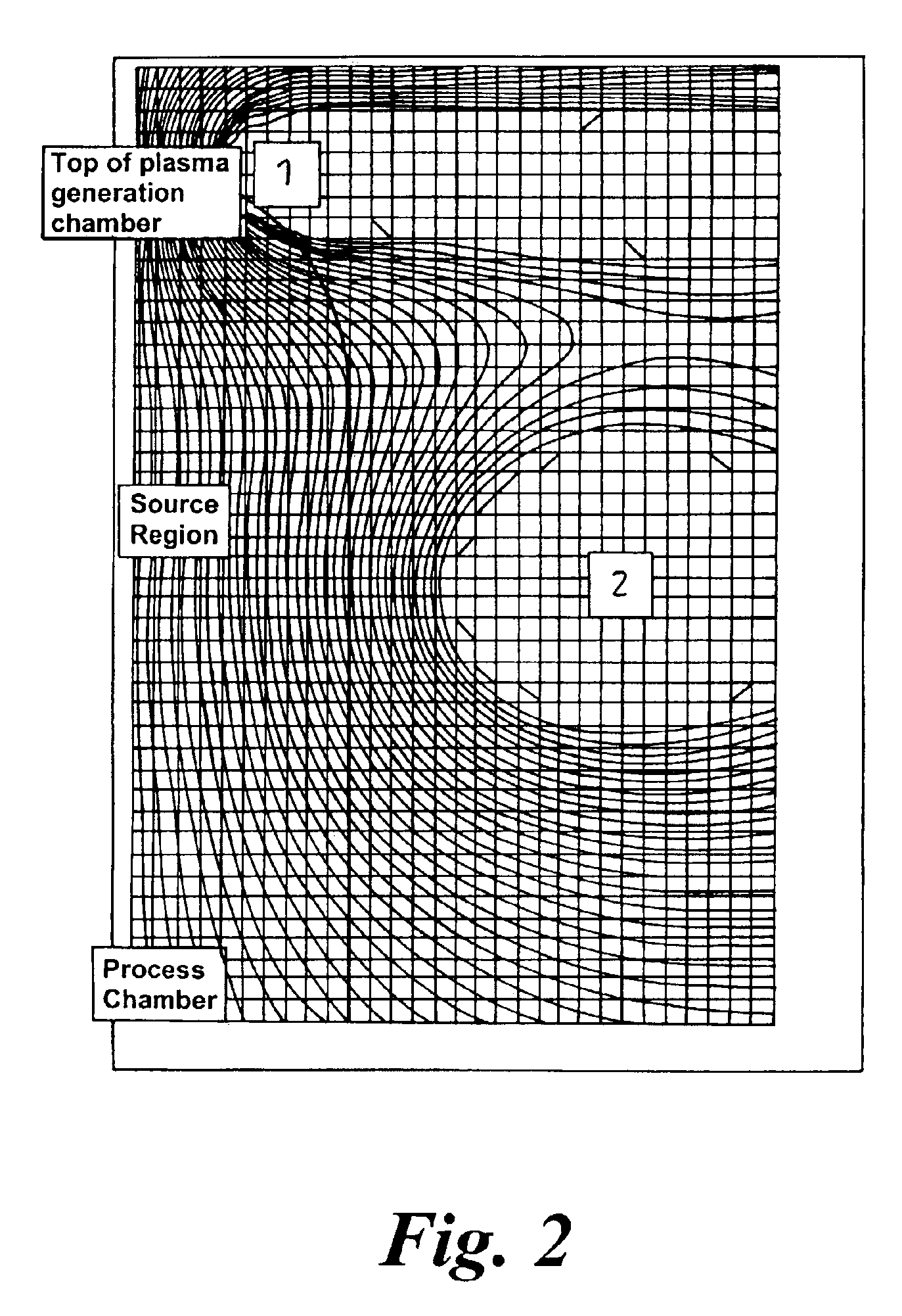
In FIG. 1 an idealised total field is indicated at 10 by plotting a magnetic field for the vertical position of an apparatus, of the type that will be described in more detail in connection with FIGS. 5 or 6, in which there is a plasma generation chamber surmounting a process chamber. As will be seen from the graph 10 the Applicants have determined that what is required is a highly uniform field in the source or plasma generation region, with a strong convergent field at the top of the plasma generation chamber and, in general, a reducing field in the process chamber. In some embodiments it may be desirable to have the field strength peak in the process chamber, before it reduces.

As has been indicated above, by selecting such a magnetic field profile, the Applicants are able to reflect the electrons, which would otherwise escape through the top of the plasma generation chamber, along the field lines and thereby trap electrons as previously described; to enhance the coupling in the s...


PUM


Abstract

This invention relates to plasma processing apparatus and in particular, but not exclusively, to inductively coupled plasma helicon or electron cyclotron resonance apparatus. A plasma generation chamber is sat above a process chamber, in which is located a workpiece support. A plasma generation or source region exists and coils are provided to create magnetic mirrors above and below the plasma generation zone, whereby electrons will be reflected back towards the plasma zone and there is no electrical conductive path extending around or through at least the upper mirror.

Description

BACKGROUND OF THE INVENTION1. Field of the InventionThis invention relates to plasma processing apparatus and in particular, but not exclusively, to inductively coupled plasma helicon or electron cyclotron resonance apparatus.2. Description of Related ArtAn early suggestion for the design of an inductively coupled plasma apparatus is described in U.S. Pat. No. 4,810,935, in which an antenna operates within an axial magnetic field upon a plasma source, which is coupled to a larger volume process chamber. This noted that, under these conditions, efficient coupling of the RF power could be achieved. This efficiency is due to the resonant response of the electrons' motions in the form of helicon plasma waves. The concept was further developed in U.S. Pat. No. 4,990,229, and other examples of helicon plasma source designs are contained in U.S. Pat. Nos. 5,449,433, 5,567,268 and 6,189,484.In an alternative approach, power is supplied radiatively to the plasma to generate an electron cyclo...

Claims


Application Information

Patent Timeline
IPC IPC(8): H01J37/32
CPCH01J37/3211H01J37/32192H01J37/32678H01J37/32623H01J37/3266H01J37/32357
Inventor APPLEYARD, NICHOLAS JOHN
Owner SPTS TECH LTD
Why Eureka
Try Eureka