Tie-back connection for subsea well

a technology of tie-back connection and subsea well, which is applied in the direction of flanged joint, borehole/well accessories, construction, etc., can solve the problems of increased corrosion, difficulty in achieving the optimum stress reaction characteristics of the stress joint, and difficulty in assembly of hydraulic actuation components or other mechanisms

Inactive Publication Date: 2006-01-26
DRIL QUIP
View PDF11 Cites 29 Cited by
  • Summary
  • Abstract
  • Description
  • Claims
  • Application Information

AI Technical Summary

Benefits of technology

[0007] A connection structure is provided between a stress joint in a riser and a tie-back connector of a subsea wellhead. The connection structure joins a stress joint of one material with a wellhead tie-ba...

Problems solved by technology

Where the upper tie back connector body and the stress joint are configured as a single piece component, difficulties can be encountered in the assembly of hydraulic actuation components or other mechanisms forming part of the tie back connector.
This problem may be encountered, for example, where hydraulic lock actuation mechanisms used for securing the riser to the wellhead must be assembled over the top of the tie-back connector.
Moreover, optimum stress react...

Method used


Image

  • Tie-back connection for subsea well
  • Tie-back connection for subsea well
  • Tie-back connection for subsea well

Examples


Embodiment Construction

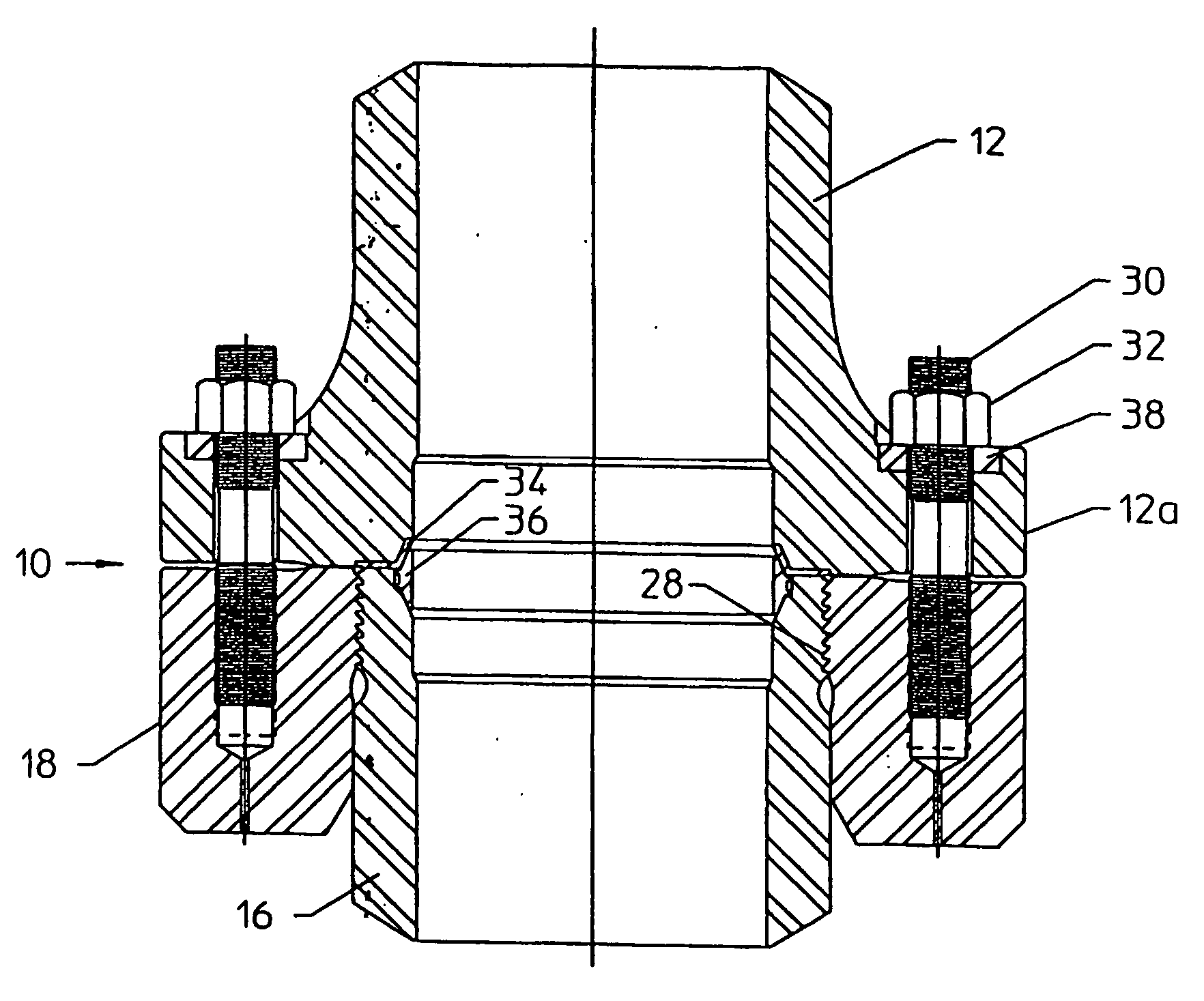
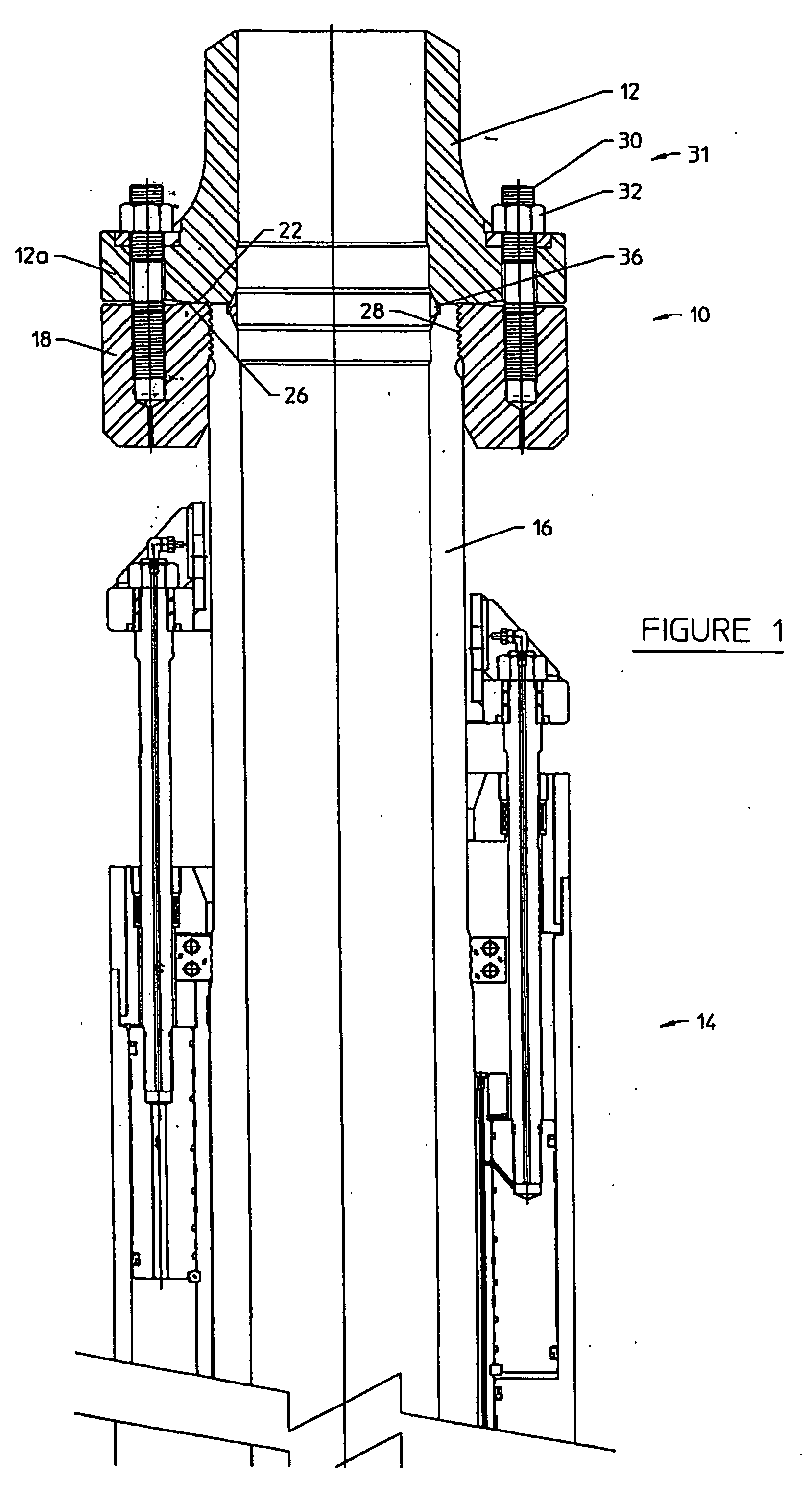
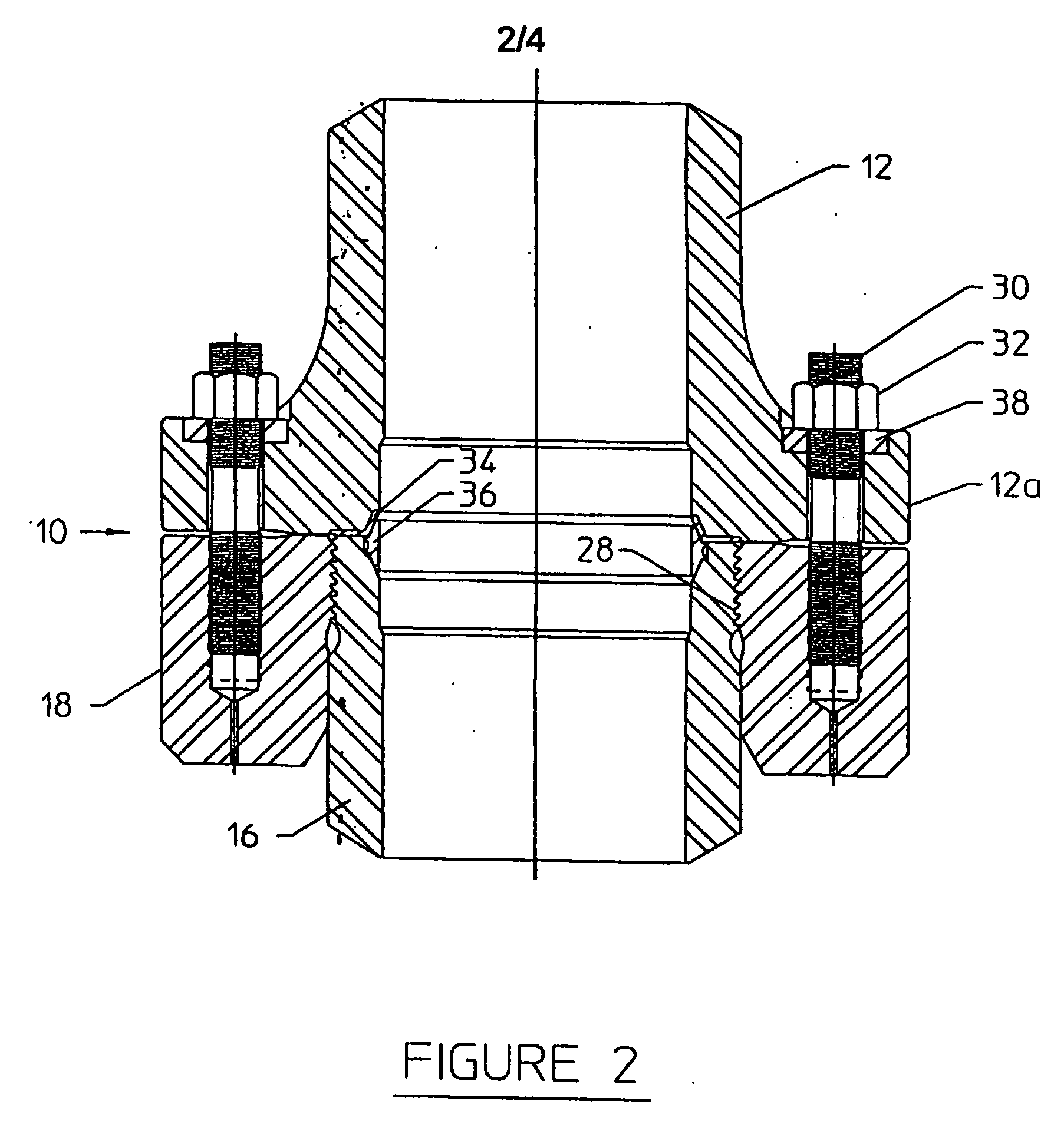
[0020]FIG. 1 illustrates a preferred embodiment of the connection structure of the present invention, indicated generally at 10, for connecting a stress joint 12 to a subsea wellhead assembly (not illustrated). An upper body of a tie-back connector, indicated generally at 14, extends toward the water surface from the subsea wellhead assembly. An example of the tie-back connector 14 is disclosed in U.S. patent application Ser. No. 09 / 954,998, now published in Pub. No. U.S. 2002 / 0096878, incorporated herein by reference for all purposes.

[0021] The tie-back connector 14 includes an elongate tubular tie-back body 16 and a tie-back flange 18 mechanically secured to the tie-back body 16. The tie-back flange 18 has a mating face 22 facing upwardly from the tie-back connector 14 for connecting to a flange 12a at the base of the stress joint 12.

[0022] The mechanical connection securing the connection structure 10 and the tie-back body 16 may comprise a threaded connection 28 between the ti...


PUM


Abstract

A connection structure is disclosed for connecting a riser to a subsea wellhead assembly. The connection structure allows components of the tie-back connector (16) to be assembled over the tie-back connector before the tie-back connector is secured to a long stress joint, to avoid the need to maneuver the components over the long stress joint. High strength materials are used in the construction of the stress joint to minimize the effects of stresses in the wellhead connector. The connection fixture provides electrical insulation (34) between the engagement points of the stress joint and the tie-back connector to minimize corrosive galvanic action. The connection structure provides an upwardly facing flange (18) that may be threaded or otherwise connected to the top of the tie-back connector and is adapted to mate with and secure to a downwardly facing flange (12a) carried at the bottom of the stress joint (12).

Description

CROSS-REFERENCE TO RELATED APPLICATIONS [0001] This application is related to and claims benefit of U.S. Provisional Application Ser. No. 60 / 409092 filed Sep. 9, 2002 and assigned to the Assignee of the present application.FIELD OF THE INVENTION [0002] The present invention relates to connectors for securing riser pipes to subsurface wellheads. More specifically, the present invention relates to an improved connection between a riser stress joint and a tie back connector. BACKGROUND OF THE INVENTION [0003] An external string of pipe is frequently used to communicate fluids and well products between a subsea wellhead and a drilling or production structure located at the water surface. This string of pipe, frequently referred to as a riser, is subjected to strong lateral and longitudinal stresses caused by water currents and motion between the surface structure and the wellhead. Because the wellhead is stationary relative to the riser, these stresses concentrate in the connection betw...

Claims


Application Information

Patent Timeline
IPC IPC(8): F16L23/00E21BE21B33/038F16L19/00F16L23/12F16L25/02
CPCE21B33/038F16L25/026F16L19/00F16L23/12
Inventor MILBERGER, LIONEL
Owner DRIL QUIP
Why Eureka
Try Eureka