Digital-to-analog converting circuit, electroopitcal device, and electronic apparatus

a digital-to-analog converting circuit and digital-to-analog technology, applied in the direction of code conversion, static indicating devices, instruments, etc., can solve the problems of substantial difficulty in realization and heavy load of signal generating circuits, and achieve accurate color reproduction of input image data for display and correct luminance of electrooptical devices

Inactive Publication Date: 2006-01-26
SEIKO EPSON CORP
View PDF24 Cites 7 Cited by
  • Summary
  • Abstract
  • Description
  • Claims
  • Application Information

AI Technical Summary

Benefits of technology

[0008] An aspect of the invention can provide a digital-to-analog converting circuit capable of readily correcting an analog current converted by digital-to-analog conversion with a simple circuit configuration, an electrooptical device, and an electronic apparatus.
[0025] An electronic apparatus according to the invention includes the electrooptical device described above. Therefore, the luminance of the electrooptical device can be corrected based on the second digital data without any complex pre-processing.

Problems solved by technology

In such cases, if the digital image data is also to be corrected in the signal generating circuit, a complex signal generating circuit is required, and the signal generating circuit has a heavy load, which is substantially difficult to realize.

Method used


Image

  • Digital-to-analog converting circuit, electroopitcal device, and electronic apparatus
  • Digital-to-analog converting circuit, electroopitcal device, and electronic apparatus
  • Digital-to-analog converting circuit, electroopitcal device, and electronic apparatus

Examples


first embodiment

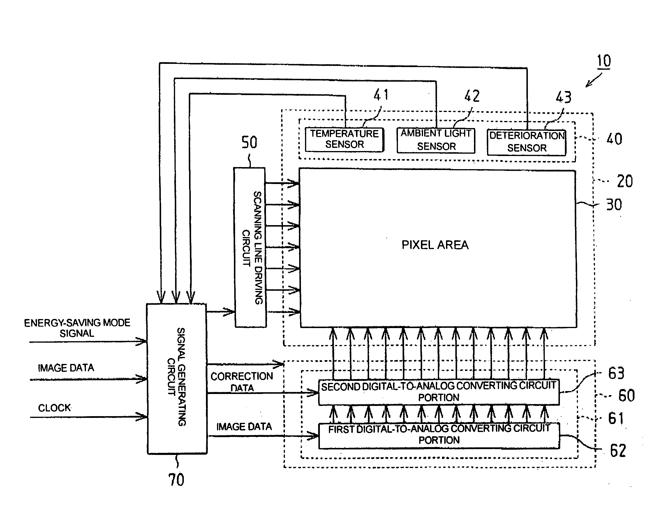
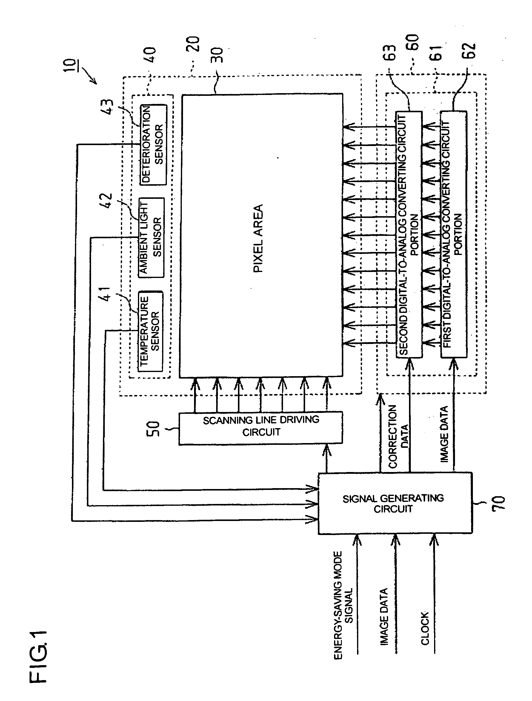
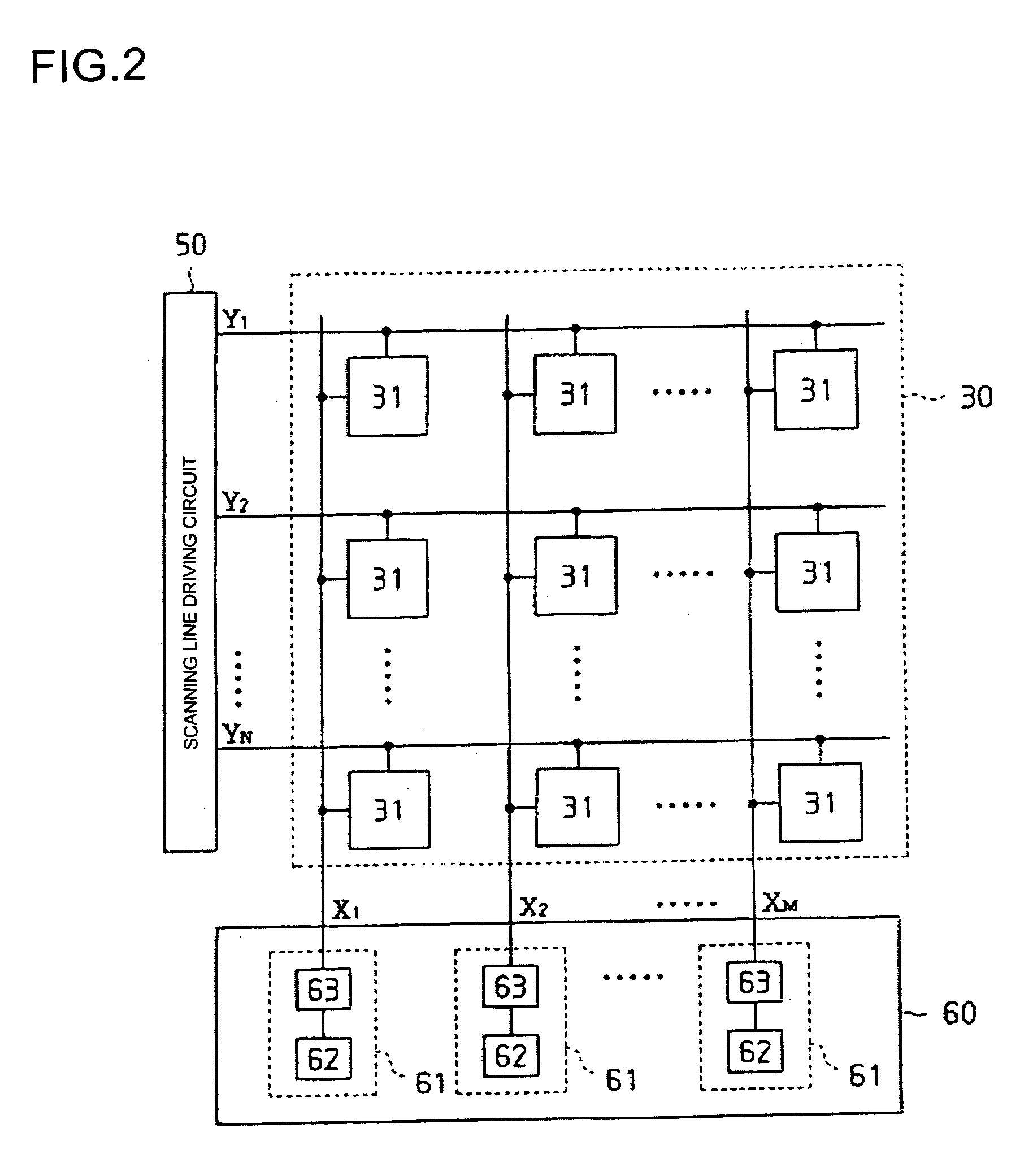
[0083] the digital-to-analog converting circuit 61 disposed for each data line Xm includes the second digital-to-analog converting circuit portion 63. Therefore, after digital grayscale data is converted into an analog current Id, the analog current Id can be corrected into a data signal (analog current) Iout based on digital current correction data without any complex pre-processing.

[0084] According to the first embodiment, the second digital-to-analog converting circuit portion 63 disposed in the digital-to-analog converting circuit 61 is composed of current mirror circuits. Therefore, the analog current Id converted from the digital grayscale data can be readily corrected into a data signal (analog current) Iout.

[0085] According to the electrooptical device of the first embodiment, the analog current Id corresponding to image data (digital grayscale data) having a gamma characteristic is corrected by the second digital-to-analog converting circuit portion 63, thus allowing for ...

second embodiment

[0088]FIG. 8(a) is an exemplary circuit diagram of a second digital-to-analog converting circuit portion 63 in a digital-to-analog converting circuit 61 and FIG. 8(b) is a timing chart of the second digital-to-analog converting circuit portion 63. In this embodiment, the current correction data is 3-bit digital data.

[0089] In FIG. 8(a), an input line 310 is connected to the output terminal T1 of the first digital-to-analog converting circuit portion 62, to which an analog current Id (first analog current) is supplied. A conversion transistor 320 (fourth transistor) and a switching transistor 331 (seventh transistor) are connected in series between a ground potential and the input line 310. A gate (fourth control terminal) and drain of the conversion transistor 320 are connected with each other via a switching transistor 332 (eighth transistor). A gate (seventh control terminal) of the switching transistor 331 and a gate (eighth control terminal) of the switching transistor 332 are ...


PUM


Abstract

Aspects of the invention can provide a digital-to-analog converting circuit capable of, after converting digital data into an analog current, correcting the current value based on digital current correction data without any complex processing. The exemplary digital-to-analog converting circuit can include a first digital-to-analog converting circuit portion and a second digital-to-analog converting circuit portion. First digital data (image data) can input to the first digital-to-analog converting circuit portion, and second digital data (current correction data) can input to the second digital-to-analog converting circuit portion. After the first digital-to-analog converting circuit portion converts the image data into a first analog current, the second digital-to-analog converting circuit portion can correct the first analog current based on the current correction data, and outputs the corrected current as a second analog current.

Description

[0001] This is a Continuation of application Ser. No. 10 / 878,548 filed Jun. 29, 2004. The entire disclosure of the prior application is hereby incorporated by reference herein in its entirety.BACKGROUND OF THE INVENTION [0002] 1. Field of Invention [0003] Aspects of the invention relates to a digital-to-analog converting circuit, an electrooptical device, and an electronic apparatus. [0004] 2. Description of Related Art [0005] Digital-to-analog converting circuits are used in a variety of electronic apparatuses. For example, a digital-to-analog converting circuit can be used in a data line driving circuit of an organic electroluminescent display device, which is one type of electrooptical device. The digital-to-analog converting circuit for use in the data line driving circuit supplies an analog current corresponding to digital image data (grayscale data) to pixel circuits via data lines. See, for example, Japanese Unexamined Patent Application Publication No. 2000-122608. SUMMARY O...

Claims


Application Information

Patent Timeline
Patent Type & Authority Applications(United States)
IPC IPC(8): H03M1/22H01L51/50G09G3/20G09G3/30H03M1/74
CPCG09G3/325G09G3/3275G09G2300/0842G09G2300/0861G09G2310/027H03M1/745G09G2320/041G09G2330/021G09G2330/022G09G2360/144G09G2320/0285G09G3/20G09G3/30
Inventor JO, HIROAKI
Owner SEIKO EPSON CORP
Why Eureka
Try Eureka