Load balancing in a virtual private network

Active Publication Date: 2006-01-26
RPX CORP
View PDF12 Cites 47 Cited by
  • Summary
  • Abstract
  • Description
  • Claims
  • Application Information

AI Technical Summary

Problems solved by technology

Given the various nodes, attributes, and connectivity described above and known in the art, complexities arise in efficient use of the system resources on the MEN and

Method used


Image

  • Load balancing in a virtual private network
  • Load balancing in a virtual private network
  • Load balancing in a virtual private network

Examples


Example

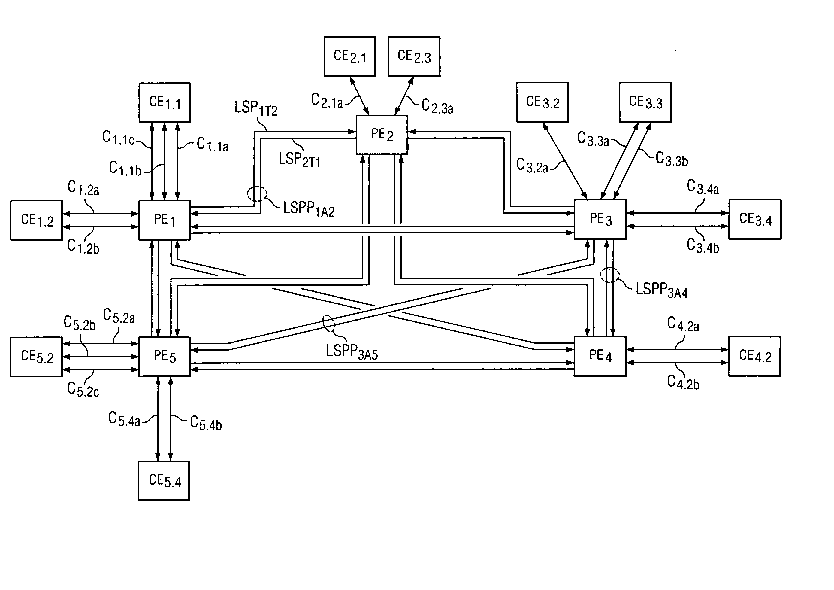
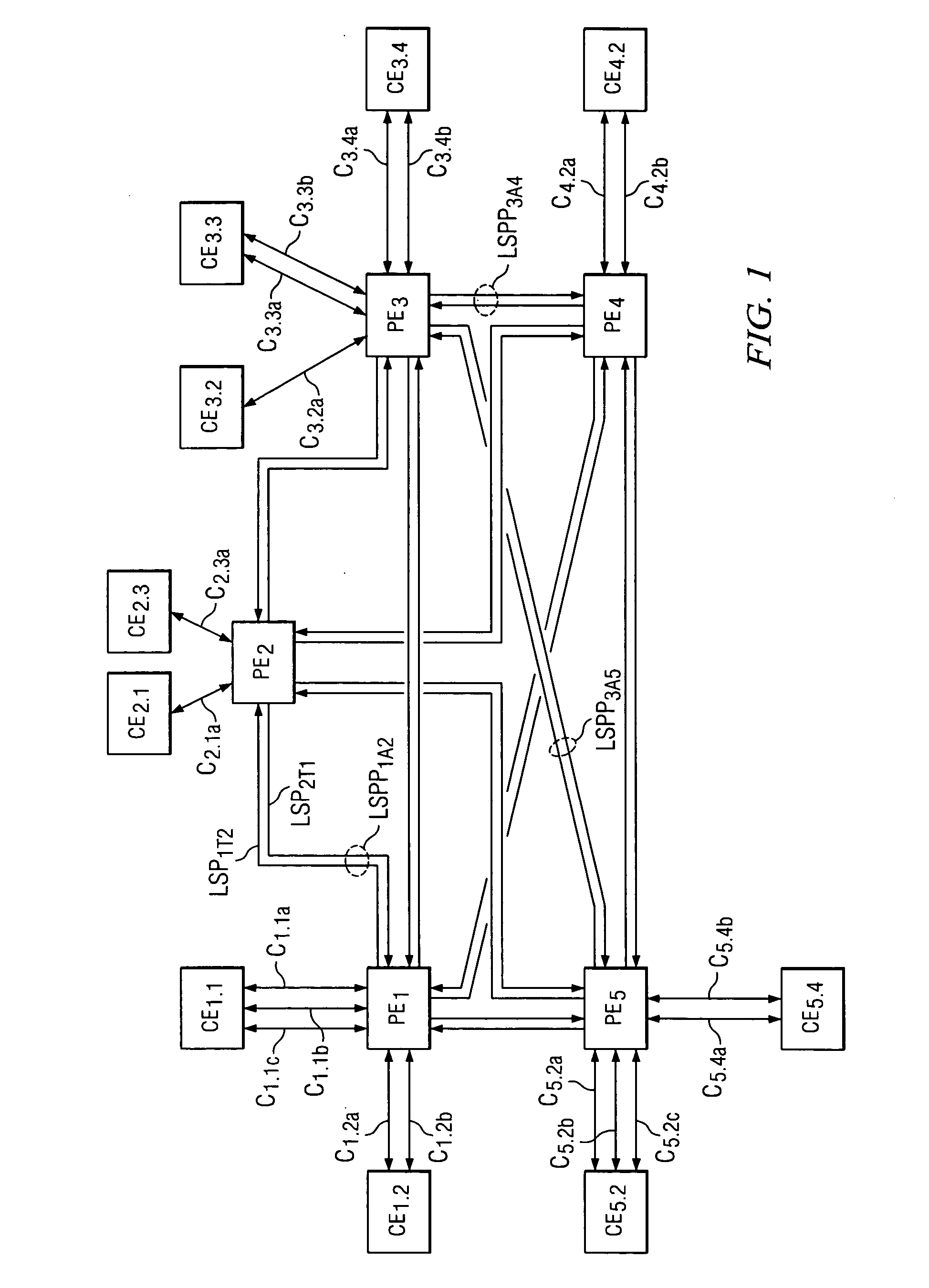
[0012] By way of introduction to various aspects of the present inventive scope, note that the preferred embodiments establish a provider-provisioned virtual private network (“PP-VPN”) that achieves load balancing in part by using its backup or protection paths to potentially carry part of the network traffic load. In other words, for traffic along a “primary” path, there is also a corresponding backup, “secondary,” or “protection” path along which traffic may be communicated should a disconnect or termination occur with respect to the primary path. To provide a context for such embodiments, a brief discussion is now provided of three known protection types. A first protection type is known as 1+1 protection, and it is characterized by requiring a completely reserved bandwidth on the backup path that is equal to that on the primary path. For example, for a channel having a primary path bandwidth of 2.2 Gbps, then 2.2 Gbps is reserved along the backup path and that path cannot be use...


PUM


Abstract

A network system (10). The system comprises a plurality of nodes (PE, CE). Each node in the plurality of nodes is coupled to communicate with at least one other node in the plurality of nodes. Further, each node in the plurality of nodes is coupled to communicate to another node via a respective primary path and via a respective backup path. Still further, each node in the plurality of nodes is operable to perform the steps of, when receiving network traffic as a receiving node, detecting delay (110, 120; 130, 140; 160, 170) in traffic received from a transmitting node, and, in response to detecting delay, communicating a signal to the transmitting node. In response to the signal, the transmitting node is operable to dynamically adjust (150; 190) a distribution of traffic through a respective primary path and a respective backup path from the transmitting node to the receiving node.

Description

CROSS-REFERENCES TO RELATED APPLICATIONS [0001] Not Applicable. STATEMENT REGARDING FEDERALLY SPONSORED RESEARCH OR DEVELOPMENT [0002] Not Applicable. BACKGROUND OF THE INVENTION [0003] The present embodiments relate to computer networks and are more particularly directed to network traffic load balancing in a virtual private network. [0004] Ethernet networks have found favor in many applications in the networking industry for various reasons. For example, Ethernet is a widely used and cost effective medium, with numerous interfaces and speed capability up to the Gbps range. Ethernet networks may be used to form a Metro Ethernet Network (“MEN”), which is generally a publicly accessible network that provides a Metro domain, typically under the control of a single administrator, such as an Internet Service Provider (“ISP”). A MEN is typically used to connect between an access network and a core network. The access network often includes private or end users making connectivity to the ...

Claims


Application Information

Patent Timeline
IPC IPC(8): H04J1/16
CPCH04L12/2852H04L12/4641H04L47/125H04L45/12H04L45/22H04L45/02
Inventor SRIDHAR, KAMAKSHIALI, MAHER
Owner RPX CORP
Why Eureka
Try Eureka