Heater with reflector and method for reflecting heat

a technology of reflector and heater, which is applied in the field of electric space heaters, can solve the problems of a relatively small space such as a room that may require hea

Active Publication Date: 2006-01-26
MARLEY ENGINEERED PRODS
View PDF14 Cites 28 Cited by
  • Summary
  • Abstract
  • Description
  • Claims
  • Application Information

AI Technical Summary

Benefits of technology

[0012] In accordance with yet another embodiment of the present invention, a method for applying radiant heat is provided. The method comprises the steps of configuring a radiant heat generating device for connection to an electrical power source, displacing a middle portion of a radiant heat reflector configuration from a substantially parabolic shape while leaving a first ex

Problems solved by technology

For a variety of reasons, a relatively sm

Method used


Image

  • Heater with reflector and method for reflecting heat
  • Heater with reflector and method for reflecting heat
  • Heater with reflector and method for reflecting heat

Examples


Embodiment Construction

[0021] The invention will now be described with reference to the drawing figures, in which like reference numerals refer to like parts throughout. An embodiment in accordance with the present invention provides a radiant heater with infrared reflectors for one or more heating elements generally configured for broad heat diffusion in a generally forward direction.

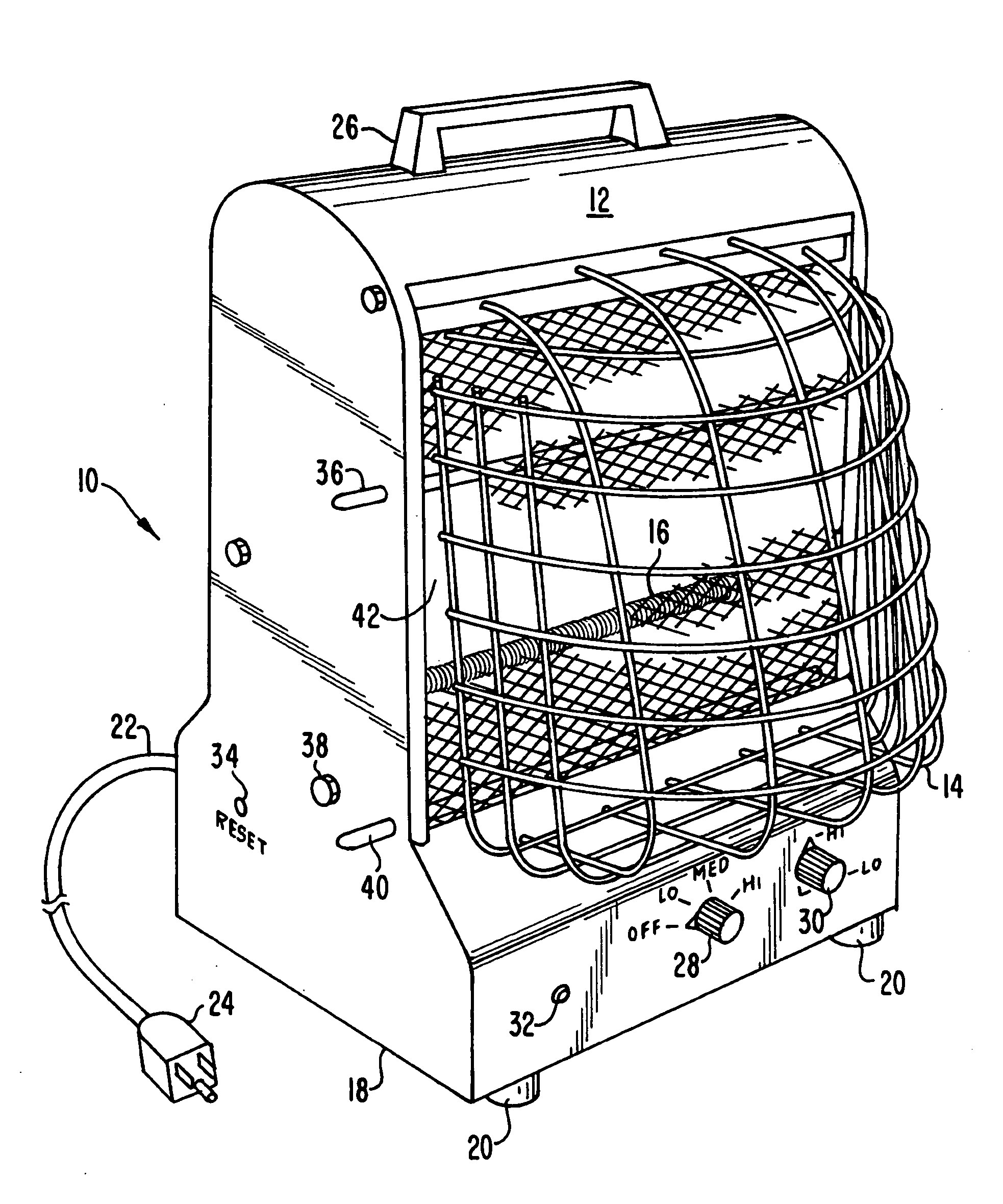
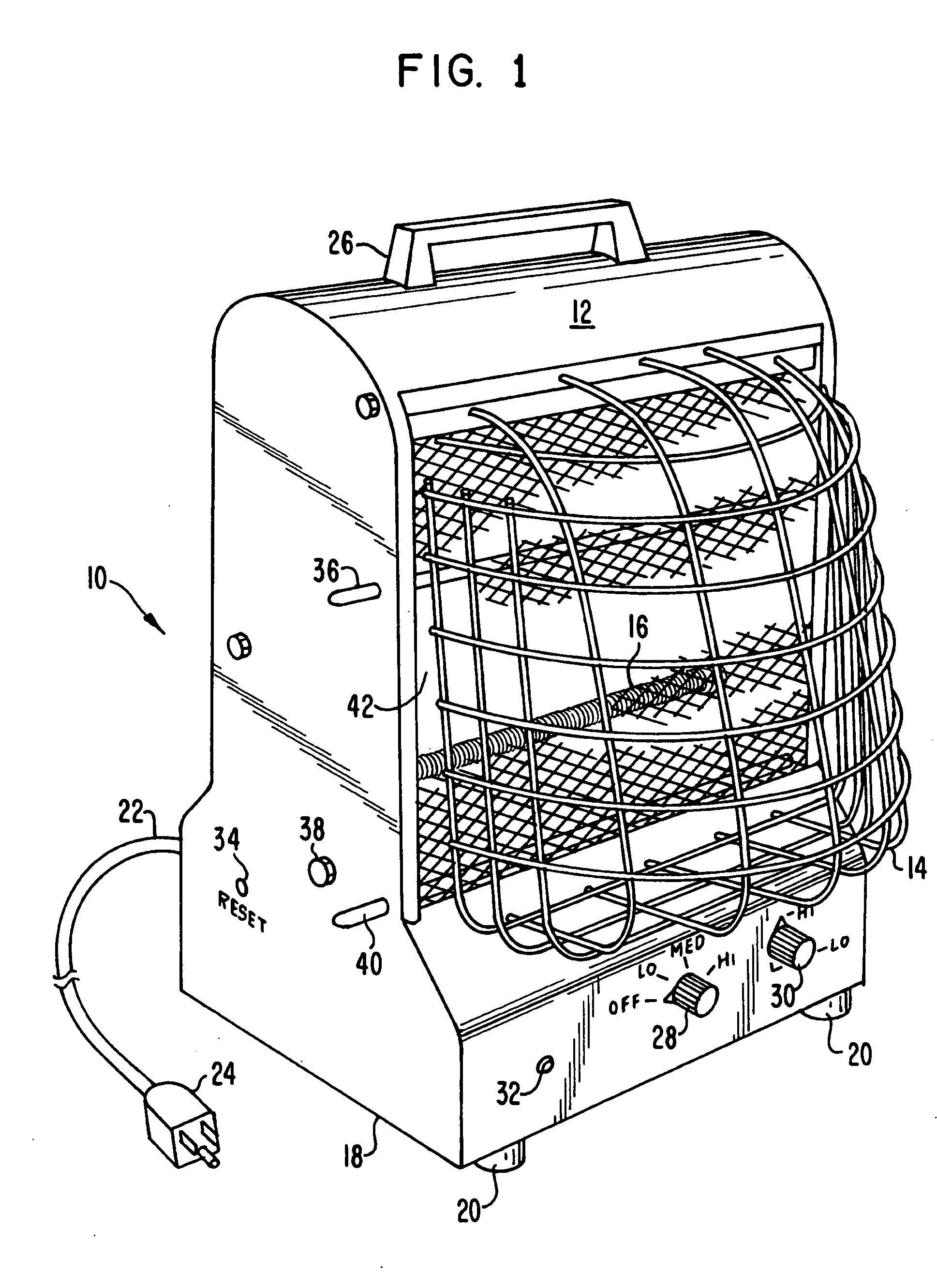
[0022]FIG. 1 is a perspective view that shows an embodiment in accordance with the present invention. Shown is a heater 10 with a housing 12, and a grille 14 that generally prevents direct access to a heating element 16. FIG. 1 also shows additional features of a heater, such as a base 18, feet 20, an electrical cord 22 with a plug 24, a handle 26, a power switch 28, a tip switch (internal), a thermostat 30, an indicator light 32, and a thermal overload 34. FIG. 1 further shows the fittings 36, 38, and 40 used to attach the defocused reflector 42 to the visible side of the housing 12 and to maintain the broad diffusion capa...


PUM


Abstract

A radiant heater includes a radiant heat source and a reflector to direct the bulk of the heat generated by the radiant source in one direction. The shape of the reflector determines the radiant pattern of the heater, and generally defocuses the output to provide a diffuse heat pattern that is substantially free of hot spots.

Description

FIELD OF THE INVENTION [0001] The present invention relates generally to electric space heaters. More particularly, the present invention relates to controlling and defining the extent of focusing of infrared radiation from a space heater product. BACKGROUND OF THE INVENTION [0002] For a variety of reasons, a relatively small space such as a room may require heat. This heat may be in addition to that furnished from existing air treatment systems. One way to provide additional heat is with an electric portable heater. One type of such space heaters is a relatively small, sometimes floor-standing, heater that is configured to run on premises distribution circuits, that is, normal household and business wiring. [0003] Heaters of various types may emit heat by radiation, convection, or conduction. A non-radiative electric heater may, for example, have one or more heating elements that release heat at comparatively low energy to raise the temperature of a quantity of air. Such heaters ma...

Claims


Application Information

Patent Timeline
IPC IPC(8): F21V7/00
CPCF24C15/22H05B2203/032H05B3/008
Inventor HINESLEY, CARL P.
Owner MARLEY ENGINEERED PRODS
Why Eureka
Try Eureka