
Image formation device

a technology of image formation and cylinder, which is applied in the direction of instruments, electrographic process equipment, optics, etc., can solve the problems of air dispersion uniformity and exhaustion, and achieve the effect of reducing noise emissions and reducing costs

Inactive Publication Date: 2006-01-26
FUJIFILM BUSINESS INNOVATION CORP
View PDF8 Cites 13 Cited by
  • Summary
  • Abstract
  • Description
  • Claims
  • Application Information

AI Technical Summary

Benefits of technology

[0016] In consideration of the problems described above, the present invention provides a low-cost image formation device with which the generation of noise such as air exhaust noise and the like is eliminated, by hot air that is spread from a fixing apparatus being dispersed to outside a housing and released without an exhaust fan being employed in a vicinity of the fixing apparatus.
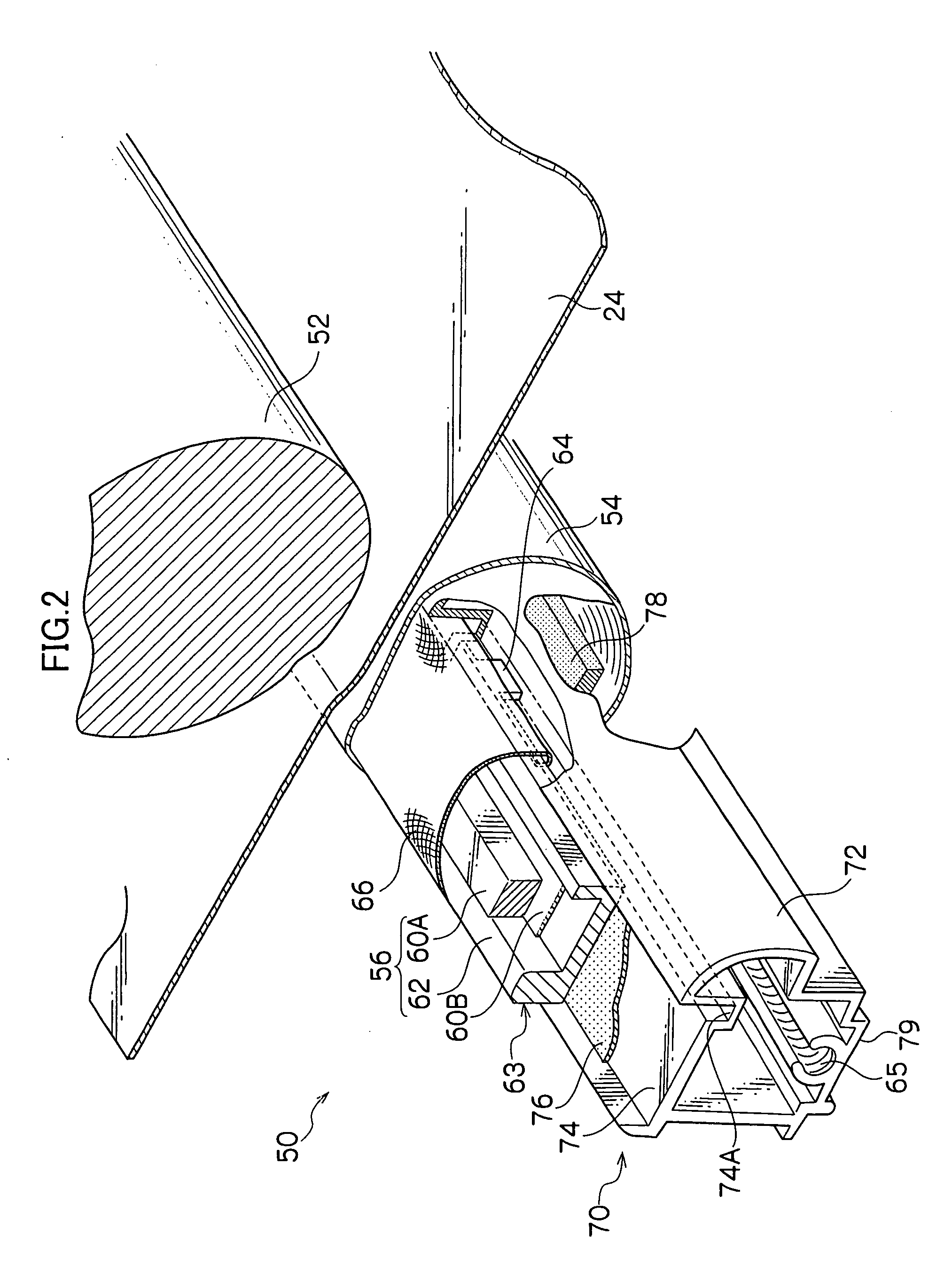
[0018] In a fanless ventilation structure image formation device with a structure as described above, the characteristic of hot air rising is utilized. The fixing apparatus is cooled by air that has entered through all the ventilation apertures at the lower portion of the cover member being subjected to heat exchange across the whole length direction length of the fixing apparatus. Hence, the warmed air rises and is exhausted uniformly from all the ventilation apertures formed in the upper portion of the cover member. Thus, natural ventilation of air in an interior portion, which is surrounded by the partition wall, the heat-shielding member and the cover member, such that efficiency of flow of the air is good can be achieved. In addition, in this fanless exchange structure image formation device, an airflow which is generated to span the whole of a width direction of the recording medium, in accordance with an operation of conveyance of the recording medium that is to be fixing-processed by the fixing apparatus along the conveyance path, contacts and cools the fixing apparatus across the length direction thereof. Hence, the warmed air rises and is efficiently exhausted uniformly from all of the ventilation apertures that are formed in the upper portion of the cover member to span the length direction of the fixing apparatus. As a result, it is possible to eliminate the necessity for provision of an exhaust fan in the image formation device, to eliminate the generation of noise such as exhaust noise and the like, to cut out a number of components relating to an exhaust fan, and to provide a product whose cost is lower by an amount corresponding to the cost of an exhaust fan. Furthermore, when air that has been employed for cooling the fixing apparatus disposed in the interior portion surrounded by the partition wall, the heat-shielding member and the cover member is being ventilated, the air that is exhausted from the interior portion is heated and includes noxious components generated during heating and fixing of toner. However, this air is dispersed uniformly and exhausted from all the ventilation apertures spanning the length direction of the fixing apparatus. Thus, this air is promptly mixed with air outside the cover member and the noxious components are rapidly dispersed and diluted. Therefore, it is possible to avoid the sensing of bad odors in the area of this image formation device.
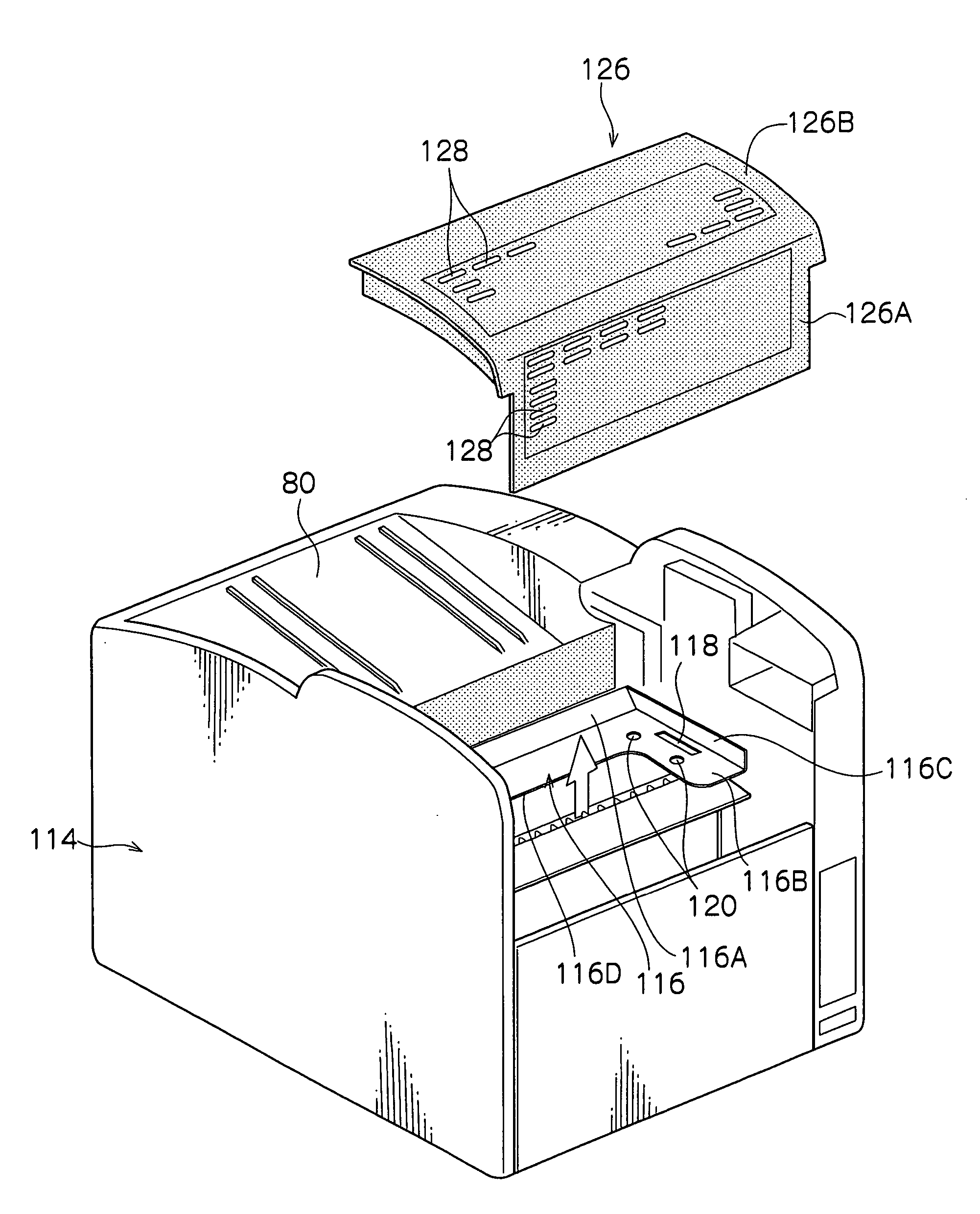
[0020] With a structure as described above, because the fixing apparatus is structured as a unit, directions of hot air spreading from the fixing apparatus are limited to predetermined directions by an exterior component of the unit itself, and the shielding portion, which is formed to extend from the lower face side of the fixing unit to the other side face side of the fixing unit, further limits directions of hot air being spread from the fixing apparatus. Thus, it is possible to limit directions of hot air being spread from the fixing unit. Furthermore, the apertures are formed in the cover member at the upper face side of the fixing unit and the one side face side of the fixing unit, which oppose the shielding portion. In addition, because the recording medium passes through the fixing unit from below to above, a direction in which the hot air is turned by the shielding portion, a direction in which the hot air is dispersed by natural convection and a direction of tensioning of the recording medium in a conveyance direction are the same direction. Thus, it is possible to release the hot air to outside the housing efficiently, without employing an exhaust fan in the vicinity of the fixing apparatus. Moreover, completely fanless ventilation in which exhaust fans are completely eliminated from the printer main body is possible.
[0022] According to an image formation device of the present invention, because hot air that spreads from a fixing apparatus is dispersed and released to outside a housing without employing an exhaust fan in a vicinity of the fixing apparatus, there is an advantage in that it is possible to eliminate emissions of noise such as air exhaust noise and the like and to provide a lower cost image formation device.

Problems solved by technology

However, this air is dispersed uniformly and exhausted from all the ventilation apertures spanning the length direction of the fixing apparatus.

Method used


Image

  • Image formation device
  • Image formation device
  • Image formation device

Examples


Embodiment Construction

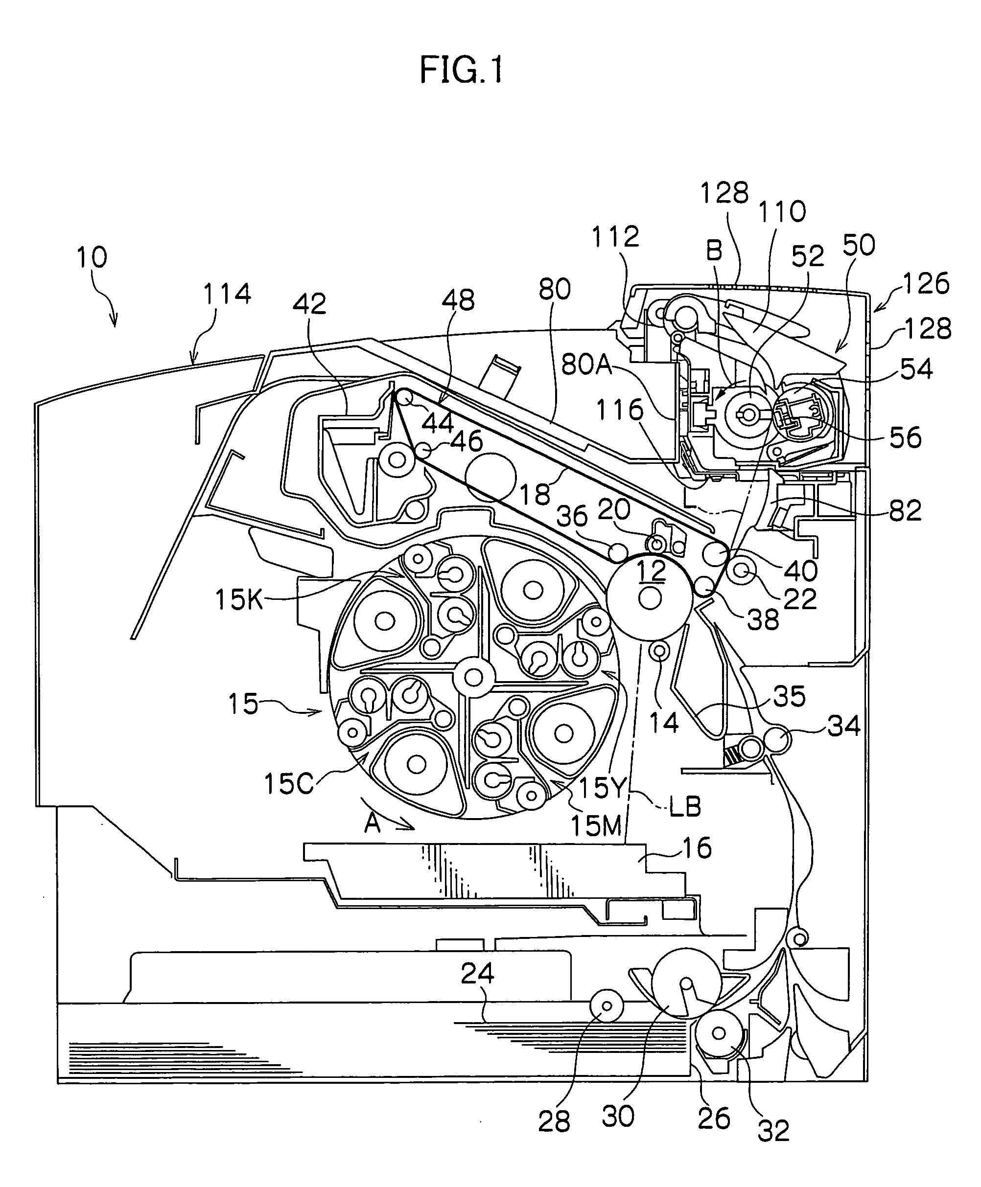
[0030] An embodiment relating to an image formation device of the present invention will be described in accordance with FIGS. 1 to 6.

[0031] A four-cycle system full-color printer serves as an image formation device which is provided with a fixing apparatus for an electrophotography system relating to the present embodiment. In this full-color printer, as shown in the schematic sectional side structural view of FIG. 1, a photosensitive body drum 12 is rotatably provided to serve as an image bearing body, somewhat toward an upper-right portion relative to the middle, of FIG. 1, inside a full-color printer main body 10. The full-color printer main body 10 is configured with a fanless ventilation structure (meaning a completely fanless ventilation structure which is not equipped with any exhaust fans at all in an image formation device main body, or a fanless ventilation structure which is not equipped with an exhaust fan for a fixing unit, in which an exhaust fan is not provided for ...


PUM


Abstract

An image formation device is provided, at which a fixing device is disposed inside a housing of a printer main body, and which is configured in a fanless ventilation structure. This image formation device is provided with a fixing unit mounting portion positioned at an upper portion of the housing, and surrounded by a partition wall and a heat-shielding member extending from a side face of the partition wall, the fixing apparatus being placed on the heat-shielding member, and the fixing unit mounting portion being isolated such that hot air will not flow to equipment inside the housing; a cover member for covering the fixing unit mounting portion; a ventilation portion which includes ventilation apertures formed through the cover member, and a conveyance portion for the recording medium.

Description

CROSS-REFERENCE TO RELATED APPLICATION [0001] This application claims priority under 35 USC 119 from Japanese patent application, No. 2004-211943, the disclosure of which is incorporated by reference herein. BACKGROUND OF THE INVENTION [0002] 1. Field of the Invention [0003] The present invention relates to an image formation device equipped with a fixing apparatus which is employed in a copying device, printer or the like, which is structured to serve as an electrophotography system. [0004] 2. Description of the Related Art [0005] Commonly, in an image formation device such as a copying device, a printer or the like that employs an electrophotography system, a photosensitive body formed in, for example, a drum shape is uniformly charged, the photosensitive body is exposed with light which is controlled in accordance with image information, and an electrostatic latent image is formed on the photosensitive body. Hence, this electrostatic latent image is made visible with toner (a ton...

Claims


Application Information

Patent Timeline
IPC IPC(8): G03G21/20
CPCG03G21/206G03G15/2017G03G15/2064G03G15/2053
Inventor ISHINO, MASAHIROSAIKI, MIKIOISHIDA, MASAMITANIOKA, YOSHIYASUDAIGO, HIROSHI
Owner FUJIFILM BUSINESS INNOVATION CORP
Learn More