Method and apparatus for continuous electrode impedance monitoring

a technology of impedance monitoring and electrode impedance, which is applied in the direction of electrocardiography, sensors, diagnostics, etc., can solve problems such as interference with the signal being recorded

Inactive Publication Date: 2006-01-26
COMPUMEDICS
View PDF13 Cites 118 Cited by
  • Summary
  • Abstract
  • Description
  • Claims
  • Application Information

AI Technical Summary

Benefits of technology

[0006] The present invention is a method and apparatus for continuously monitoring a test signal while simultaneously acquiring a physiological signal. The impedance test methods currently employed in electrophysiological recording equipment cause interference to the signal being recorded because the test signal has a frequency (or frequencies in the case of non-sinusoidal test waveforms) within the frequency band of t

Problems solved by technology

The impedance test methods currently employed in electrophysiological recording equipment cause interference to the signal being recorded because the

Method used


Image

  • Method and apparatus for continuous electrode impedance monitoring
  • Method and apparatus for continuous electrode impedance monitoring
  • Method and apparatus for continuous electrode impedance monitoring

Examples


Embodiment Construction

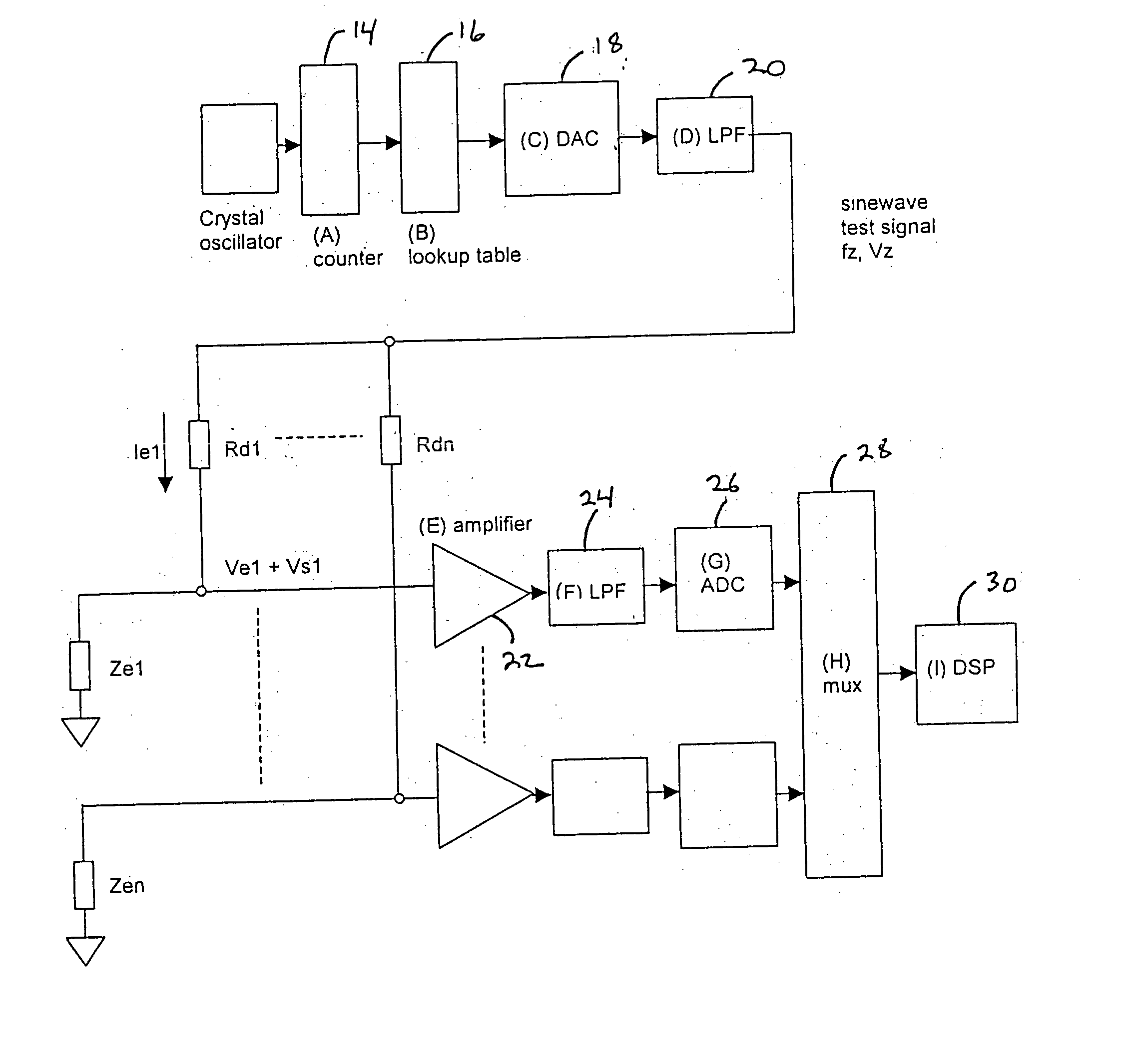
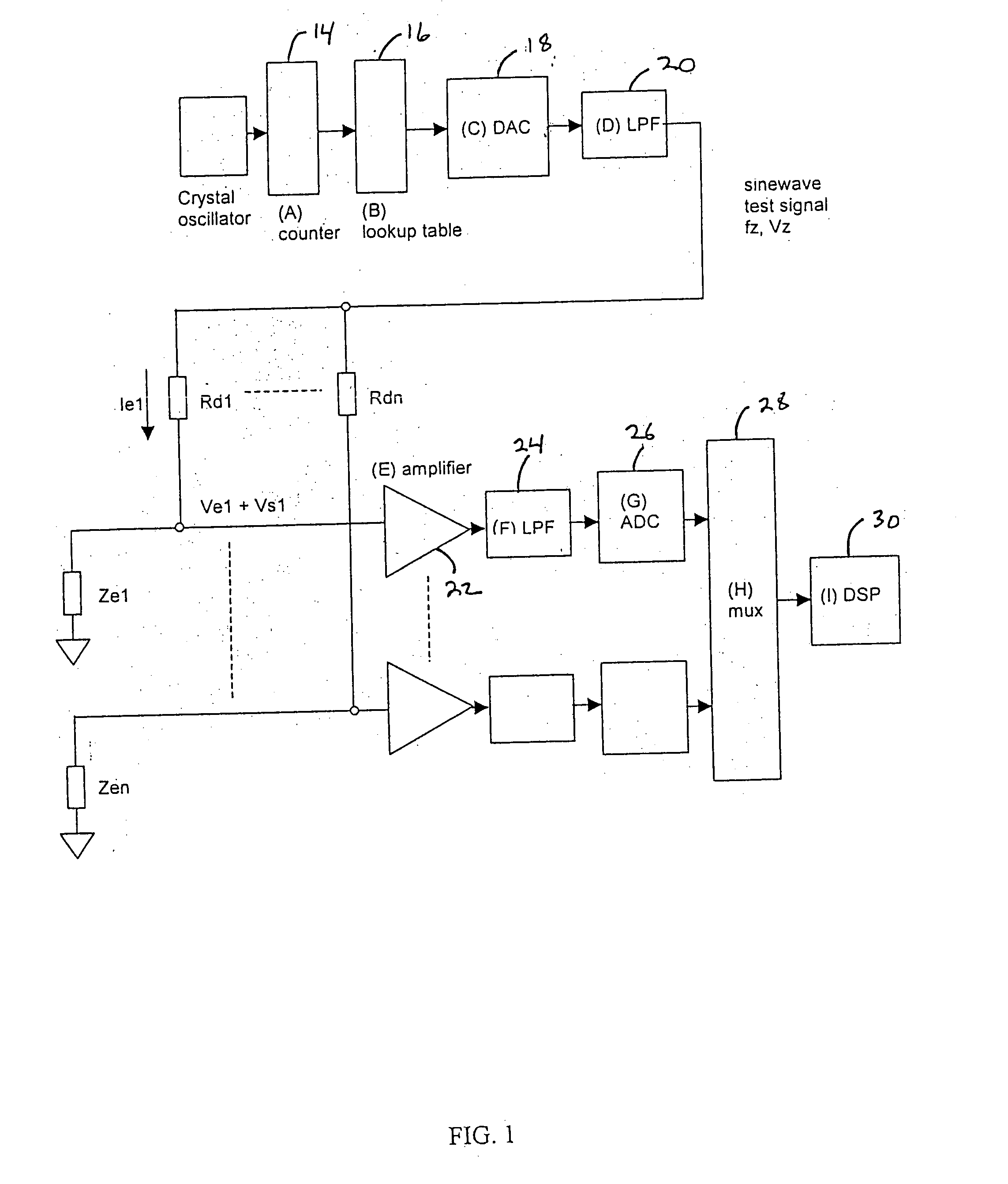
[0015] The present invention is a method and apparatus for change in electrode impedance monitoring via a combined test and physiological signal. While the embodiment disclosed is particularly adapted to monitor contact impedance and EEG, ECG, EOG, or EMG signals, one skilled in the art can readily adapt the present invention to monitor different parameters, which involve the testing of a sensor that is acquiring a physiological signal.

[0016] As shown in FIG. 1, in one embodiment, the present invention includes a test signal generator capable of producing an impedance test signal comprising of a sine wave having a known frequency, fz 3, which is slightly higher than the frequency range of the electrophysiological signal being monitored. A crystal oscillator 12 provides a known, frequency stable signal to clock the input of a counter 14. The counter output sequentially accesses a lookup table 16 which can be implemented using any digital storage device such as an EPROM or RAM, conta...


PUM


Abstract

In one embodiment, the present invention includes a test signal generator capable of producing an impedance test signal comprising of a sine wave having a known frequency. The test signal generator may include a crystal oscillator, a counter, and a lookup table. The lookup table output is applied to a digital to analog converter and is then low pass filtered using a conventional analog filter to produce a sine wave of a known frequency and voltage amplitude. The test signal flows through the electrode and combines with an electrophysiological signal to form a combined signal. A signal processor is used to isolate the combined signal into the test signal component and the electrophysiological component. The signal processor digitally low pass filters the combined signal and the output of the low pass filter is the electrophysiological signal. The signal processor then digitally bandpass filters the combined signal using a filter with a center frequency which is the same as the test frequency. The output of this filter is then used to calculate the electrode impedance.

Description

FIELD OF THE INVENTION [0001] Generally, the present invention relates to a method and apparatus for ensuring the accuracy of an acquired physiological signal. More specifically, the present invention is a method of monitoring electrode impedance while receiving an electromagnetic physiological signal. BACKGROUND OF THE INVENTION [0002] Physiological monitors will often have a testing procedure to check whether the interface between a sensor and the patient being monitored is adequate to acquire a physiological reading. This is especially true with regards to the acquisition of an electrophysiological signal. Typically, an electrophysiological signal is acquired through an electrode which is attached to the patient. The contact between an electrode and a patient's skin can significantly affect the results of an electrophysiological signal. High contact impedance generally causes poor quality recordings due to power interference. [0003] It is a common practice to measure the electrod...

Claims


Application Information

Patent Timeline
IPC IPC(8): A61B5/04
CPCA61B5/04A61B5/6843A61B5/0424A61B5/24A61B5/276
Inventor FREEMAN, WARWICKGRASSO, PHILIPNEWMAN, RICHARD
Owner COMPUMEDICS
Why Eureka
Try Eureka