Acoustic signal transmission method and acoustic signal transmission apparatus

a transmission method and signal technology, applied in the field of acoustic transmission methods and apparatuses, can solve the problems of unavoidable complexity in inability to use methods, and possible misunderstanding of original intended meaning, so as to increase the enjoyment of actively listening, simplify the overall apparatus configuration, and reduce the cost

Inactive Publication Date: 2006-01-26
NIPPON TELEGRAPH & TELEPHONE CORP
View PDF16 Cites 14 Cited by
  • Summary
  • Abstract
  • Description
  • Claims
  • Application Information

AI Technical Summary

Benefits of technology

[0011] Therefore, an object of the present invention is to provide means to easily transmit sounds (audible sound signals) that can be heard by humans and animals and to simultaneously transmit associated information signals. Also, the present invention has an object to provide various systems based on the information transmission means.

Problems solved by technology

That is, a total of more than two apparatuses are necessary, and complexity in the overall apparatus configuration is unavoidable.
Also, apart from this problem, although there are methods of signal transmission based on ultrasonic waves as carrier waves, because ultrasonic sounds cannot be heard by human ears, it is necessary to convert to an audible sound at the receiver side, and the method cannot be used for the above purpose.
However, according to this method, sounds that are not needed to be heard and are not of any interest to humans can be heard clearly as background noise.
Therefore, it is very disturbing, and possibilities exist of misunderstanding the intended meaning of the original sounds represented by the audible sound signals.
Therefore, such methods cannot be said to be suitable as sound-based information transfer means.

Method used


Image

  • Acoustic signal transmission method and acoustic signal transmission apparatus
  • Acoustic signal transmission method and acoustic signal transmission apparatus
  • Acoustic signal transmission method and acoustic signal transmission apparatus

Examples


embodiment 1

[0087] First, examples in Embodiment 1 will be explained.

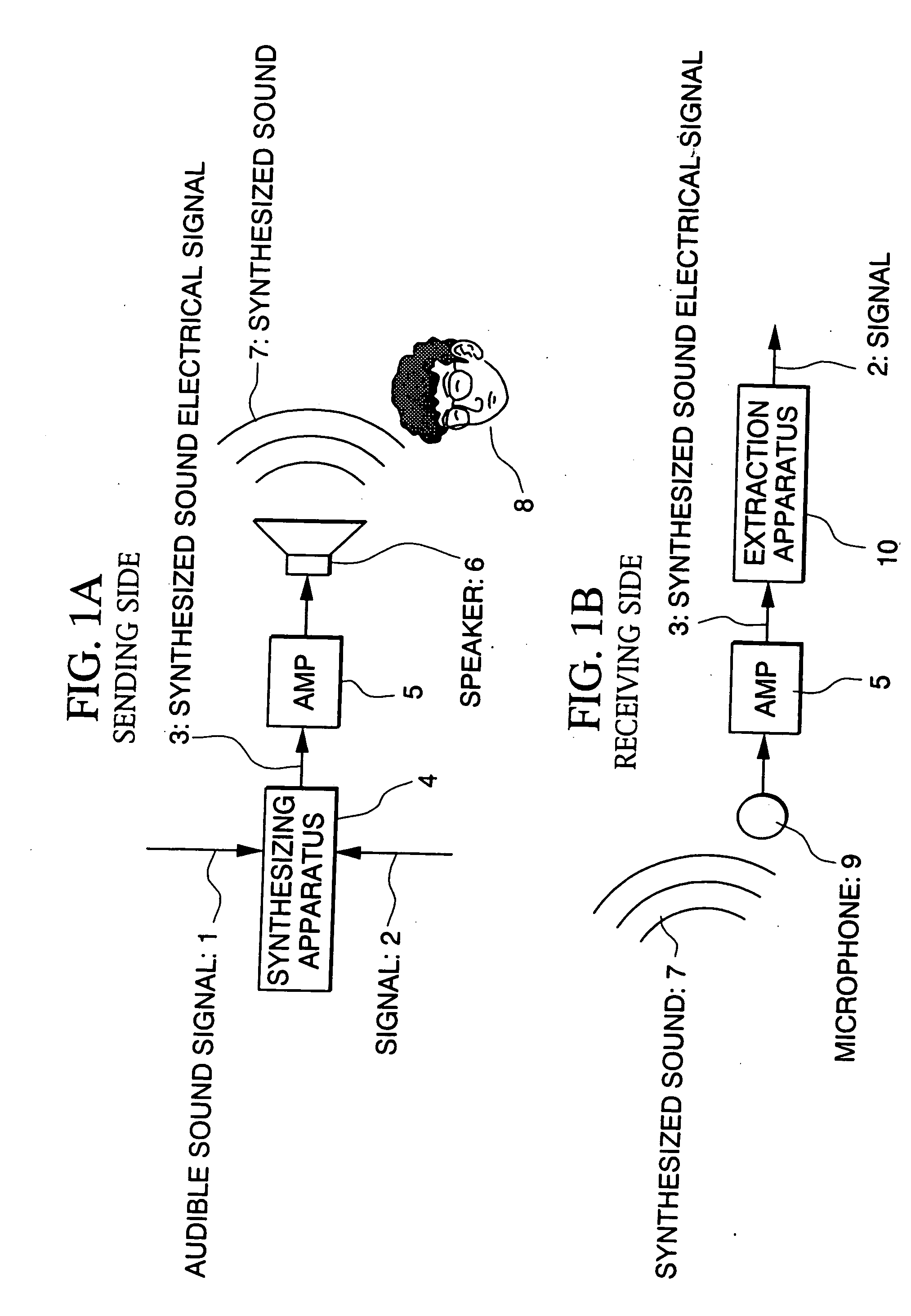
[0088]FIGS. 1A and 1B are diagrams to show Embodiment 1 of the present invention, and numeric symbol 1A refers to the sending side and 1B refers to the receiving side. In FIG. 1A, numeric symbol 1 represents audible sound signal, 2 an insertion signal, which is another signal different than the audible sound signal 1, and 3 a synthesized sound electrical signal.

[0089] Although the following explanations relate to a case of using a digital signal for signal 2, but even if the signal 2 is an analogue signal, once the signal has been converted to digital information by processing the signal through an A / D converter, it is obvious that it can be handled in the same manner as digital signals.

[0090] Also, 4 represents a synthesizing apparatus, 5 an amplifier (in FIG. 1A, it is recited as AMP), 6 a speaker, 7 a synthesized sound, 8 a person. In FIG. 1B, numeric symbol 9 represents a microphone, 10 an extraction apparatus, and othe...

embodiment 2

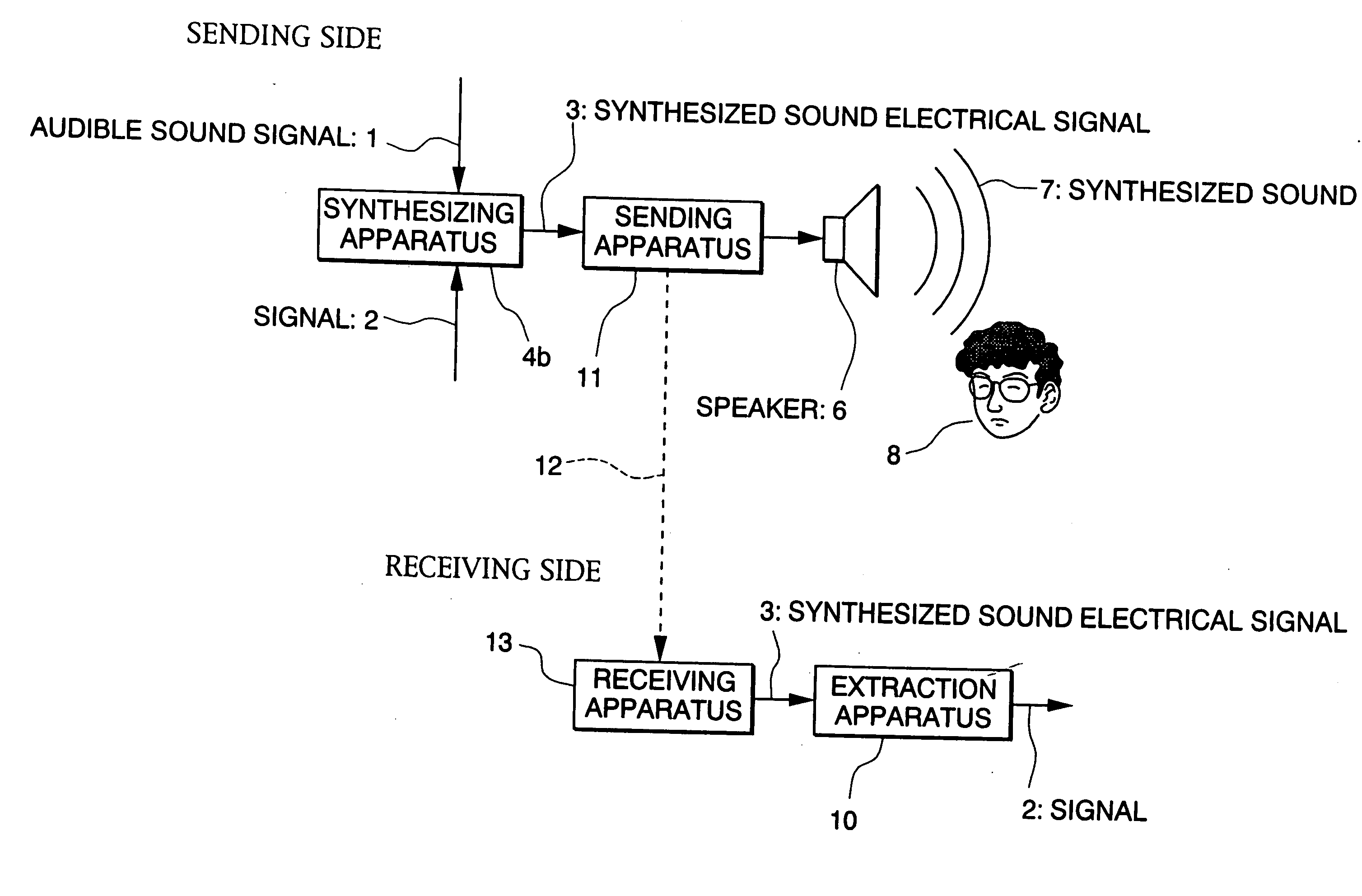
[0108]FIG. 6 shows Embodiment 2 of the present invention, which shows both the sending side and the receiving side. In the diagram, numeric symbol 1 represents an audible sound signal; 2 a signal different than the audible sound signal; 3 a synthesized sound electrical signal; 4b a synthesizing apparatus; 6 a speaker; 7 a synthesized sound; 8 a person; 10 an extraction apparatus; 11 a sending apparatus; 12 a signal transmission path; and 13 a receiving apparatus.

[0109] An outline of the flow of the signal in FIG. 6 will be explained. A feature of the present embodiment is that, as illustrated in the diagram by a dotted line, there is a means for transmitting (signal transmission path 12) the synthesized sound 7 from the sending side to the receiving side directly without propagating through the air space. In this case, an advantage is that, because acoustic noise in the air space is not mixed in the sending signal, reliability of signal transmission is increased. Also, at the same ...

embodiment 3

[0130] Embodiment 3 will be explained in the following. In Embodiment 3, a voice response machine that can respond to audio control signals is realized by applying the present invention to machine control.

[0131] Media for enabling wireless remote control, without connecting a machine to be controlled and a control apparatus directly by means of conductive wires, such as electrical waves, infrared radiation, light and sound waves, have long been known and used. Of these, a representative method using sound waves in the audible frequency band is a based on commands comprised by synthesized sound signals that can be processed readily by machines.

[0132] Such methods based on commands by synthesized sound signals that can be easily understood by machines have the advantage that recognition rate is higher than a method based on natural language, but the commands are difficult to be understood directly by humans.

[0133] For this reason, in a communication air space in which machines and ...


PUM


Abstract

The acoustic signal transmission method is based on generating a synthesized sound electrical signal by electrically synthesizing an audible sound signal and another signal different than the audible sound signal at the sending side, and transmitting the synthesized sound electrical signal, and extracting the another signal different than the audible sound signal from the synthesized sound electrical signal at the receiving side. Here, generation of the synthesized sound electrical signal is made by using a data hiding technique, for example. Accordingly, the acoustic signal represented by the synthesized sound electrical signal can be heard by human ears in the same way as the audible sound signal, and the synthesized another signal cannot be detected by human ears. Here, the synthesized sound electrical signal can be transmitted as a sound wave in air space, as electrical signal through a transmission line or as radio signals such as infrared and electromagnetic waves. It is also possible to transport or distribute the synthesized sounds by recording on recording media such as compact disc and DVD. Also, using the signal extracted from the synthesized sound electrical signal, applications such as controlling machines such as robot, transmitting text data such as information for car navigation systems, computer network addresses and commercial business information.

Description

BACKGROUND OF THE INVENTION [0001] 1. Field of the Invention [0002] The present invention relates to an acoustic transmission method and an apparatus for transmitting signals using sound waves as the transport medium. [0003] This application is based on patent application Nos. Hei 11-329914, Hei 11-356827. Hei 11-363811, Hei 11-366345, Hei 11-366346, 2000-136716, 2000-136717, 2000-248800 filed in Japan, the contents of which are incorporated herein by reference. [0004] 2. Description of the Related Art [0005] Conventionally, when transmitting the sound that can be heard by humans or animals (audible sound signals) and associated information signals concurrently to some machine, the audible signal and the associated information signal are sent through separate channels. [0006] For example, audible signal and information signal are sent as electrical signal to modulate the carrier wave, and are sent to the receiver side through electromagnetic waves and other media such as cables, and...

Claims


Application Information

Patent Timeline
Patent Type & Authority Applications(United States)
IPC IPC(8): G10L13/00G01C21/00G01C21/36G10L19/00H04H1/00H04H20/31H04H20/34H04H20/93
CPCG01C21/3629G10L19/018H04H2201/50H04H20/34H04H20/93H04H20/31
Inventor IWAKI, SATOSHINAKAYAMA, AKIRAMACHINO, TAMOTSUKITAGISHI, IKUONAKAMURA, YUKIHIRO
Owner NIPPON TELEGRAPH & TELEPHONE CORP
Why Eureka
Try Eureka