Cooling apparatus

Active Publication Date: 2006-02-02
ESPEC CORP
View PDF12 Cites 9 Cited by
  • Summary
  • Abstract
  • Description
  • Claims
  • Application Information

AI Technical Summary

Benefits of technology

[0027] Furthermore, because two types of air, including the air supplied from the air supply means and the discharged air from the compressed air supply means, can be supplied separately and independently with respective supply means, the total heat removal capacity for removing heat generated by the device is increased. Moreover, the amount of each type of air can be set with a certain degree of freedom and heat generated by the device can be divided at an appropriate ratio and removed. As a result, for example, if the amount of heat to be removed by the discharged air is set considerably smaller than the amount of heat to be removed by the supplied air, the amount of heat removed from the device by cooling can be finely adjusted and the device temperature can be accurately brought to the target temperature, for example, by maintaining the amount of supplied air at a level close to the maximum amount and changing the amount of the discharged air.
[0028] As described above, in order to obtain a cooling effect by both the air blow cooling and the cooling by compressed air discharge, a flow state is realized such that identical gases cross each other due to the flow speed difference. Therefore because only air is used, the cooling medium system is greatly simplified. Also, with the low-cost cooling apparatus using little additional equipment, a considerable amount of the heat from the devices generating a large amount of heat of up to 300 W, which could not be handled by the conventional apparatuses, can be reliably removed and operation can be ensured such that the temperature is maintained at a target temperature of, for example, about 150° C. as required for a burn-in test of the device.
[0029] With the second aspect of the invention, the cooling apparatus comprises a temperature detection means for detecting the temperature of the semiconductor device, a compressed air flow rate adjustment means capable of adjusting the flow rate of the compressed air, and a control means for controlling the compressed air flow rate adjustment means so that the temperature detected by the temperature detection means becomes the target temperature. Therefore, when a cooling effect of the device attained through these means is stabilized by maintaining constant operation conditions, the device can be automatically cooled to the target temperature with good accuracy without controlling or adjusting the air supply means. Therefo

Problems solved by technology

However, with the above-described conventional apparatus of a generic hot air circulation system, because the one surface of the device is cooled directly using one type of air, the cooled surface area and/or the amount of cooling air is insufficient and the large amount of heat generated by the device cannot be removed.
For reasons such as these, in the end the cooling effect for the element generating a large amount of heat is not sufficient.
With this system, because air inside and outside of the heat sink has been separated by the central space, the air on each side does not mix directly and so mutually independent cooling effects can be produced, but such a system can only be used for special devices that have a hole such as a central space, and although air flow is at higher pressure than it would be with a blower, because it is being pushed by an air blower tha

Method used


Image

  • Cooling apparatus
  • Cooling apparatus
  • Cooling apparatus

Examples


Example

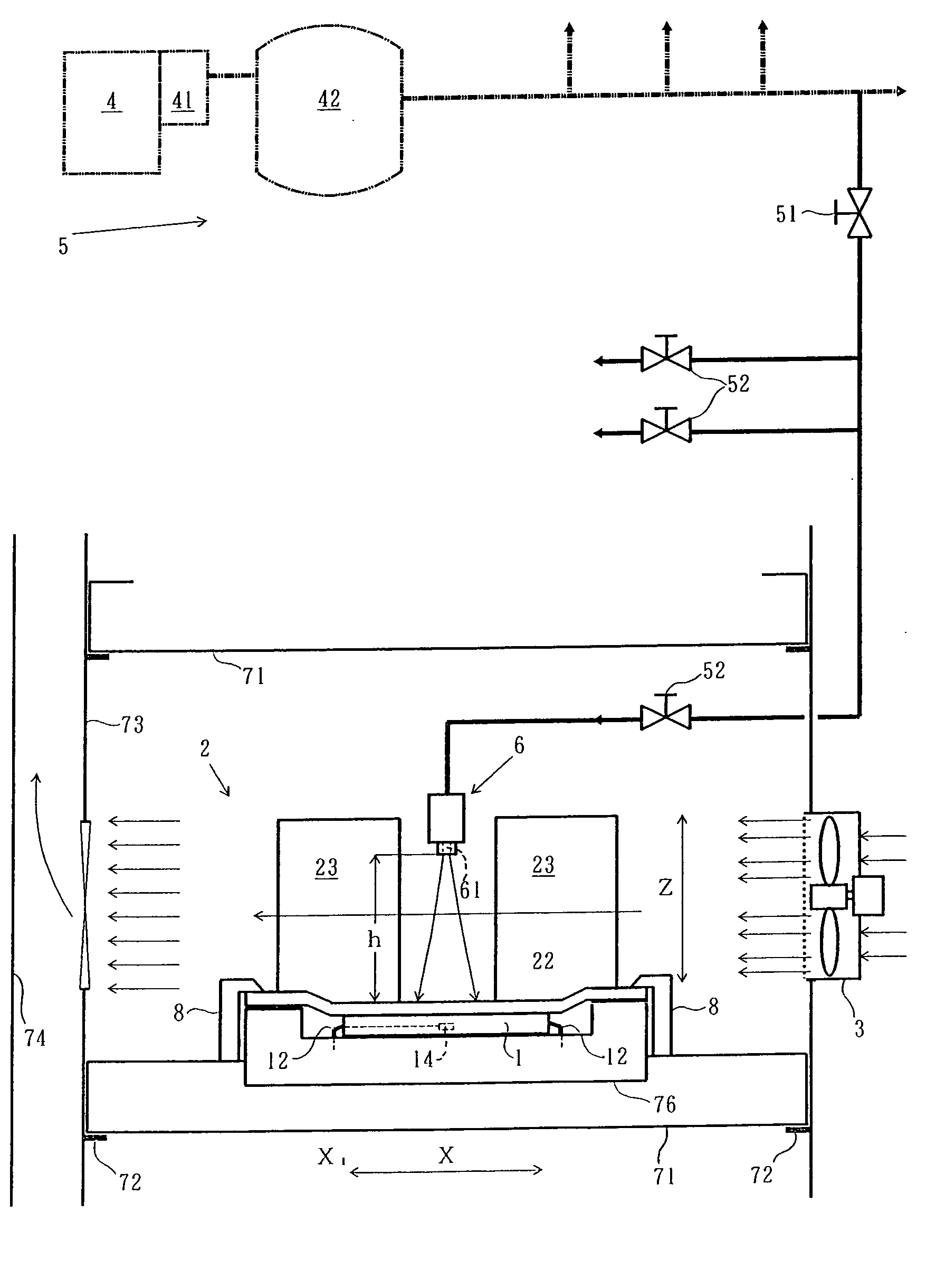
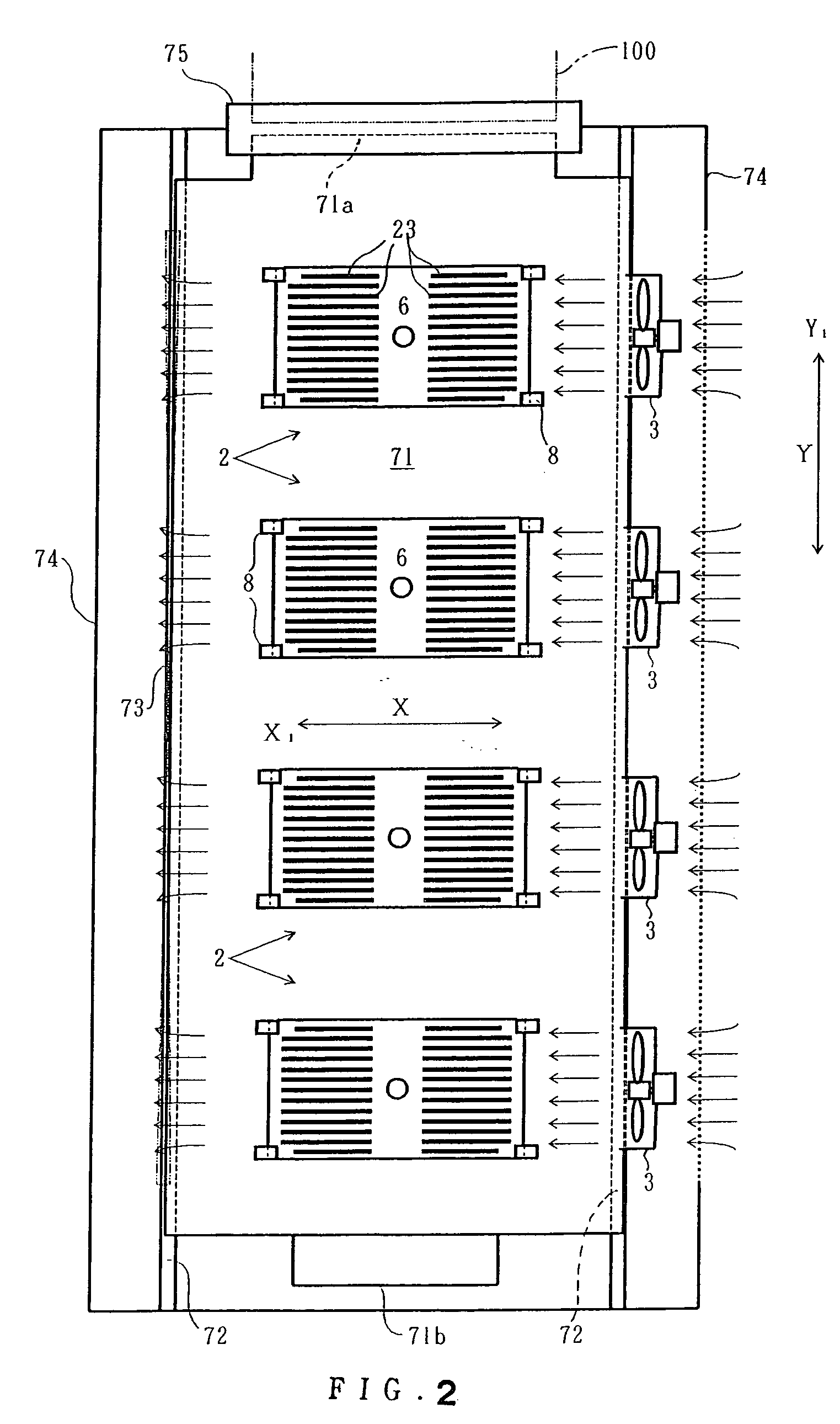
[0041] FIGS. I and 2 show examples of the entire structure of the cooling apparatus employing the present invention. FIG. 3 shows a configuration example thereof. FIGS. 1 and 2 show portions of one stage of the apparatus having a multistage configuration usually comprising 5-10 stages. Other stages are configured identically.

[0042] The cooling apparatus of the present example is an apparatus employed in a burn-in test of a device 1 that comprises an upper surface 11, in the present example a flat one surface, and that is formed so that it generates heat when electric current is passed therethrough up to a temperature higher than a temperature t, in the present example about 150° C., as the target temperature, and the temperature of the upper surface 11 also rises accordingly, this cooling apparatus being capable of cooling the device 1 to the temperature t. This cooling apparatus comprises a cooling body 2, a blower 3 as an air supply means, a compressor 4 comprising a compressed a...


PUM


Abstract

A cooling apparatus configured such that a cooling body provided with heat-dissipating plates is pressed against a device to which a socket of a burn-in board is attached, and air is provided by a blower such that the air passes between the heat-dissipating plates, and compressed air provided from a compressed air supply system is discharged by a nozzle so that it directly hits a portion of the cooling upper surface of the cooling body. By means of the cooling effects from these two types of air, a device generating a large amount of heat can be cooled with good temperature accuracy.

Description

BACKGROUND OF THE INVENTION [0001] The present invention relates to a cooling apparatus capable of conducting cooling so as to obtain the target temperature of a semiconductor device that comprises a plane-like surface and generates heat to above the target temperature and has the temperature of the one surface rising when electric current is passed therethrough. [0002] A burn-in apparatus for semiconductor devices (referred to hereinbelow as “devices”) is generally known in which a multiplicity of devices are mounted on burn-in boards, the boards are stacked in multiple stages in a temperature controlled chamber, electric current is passed through the devices, and hot air with a temperature adjusted to the fixed temperature, for example 125° C., is caused to flow parallel to the burn-in boards inside the chamber and circulate, while uniformly cooling the multiplicity of devices (see, for example, Patent References 1, 2). With such a burn-in apparatus, in the case of conventional de...

Claims


Application Information

Patent Timeline
IPC IPC(8): F28D3/00F25D23/12F28D5/00
CPCH01L23/467H01L2924/0002H01L2924/00G01R31/26H05K7/20
Inventor SHIMADA, TETSUYAWATABE, KATSUHIKO
Owner ESPEC CORP
Why Eureka
Try Eureka