
Re-usable structure which attaches to the same filter head as originally intended to receive a throw-away spin-on

Inactive Publication Date: 2006-02-02
STIFELMAN JACK
View PDF5 Cites 17 Cited by
  • Summary
  • Abstract
  • Description
  • Claims
  • Application Information

AI Technical Summary

Benefits of technology

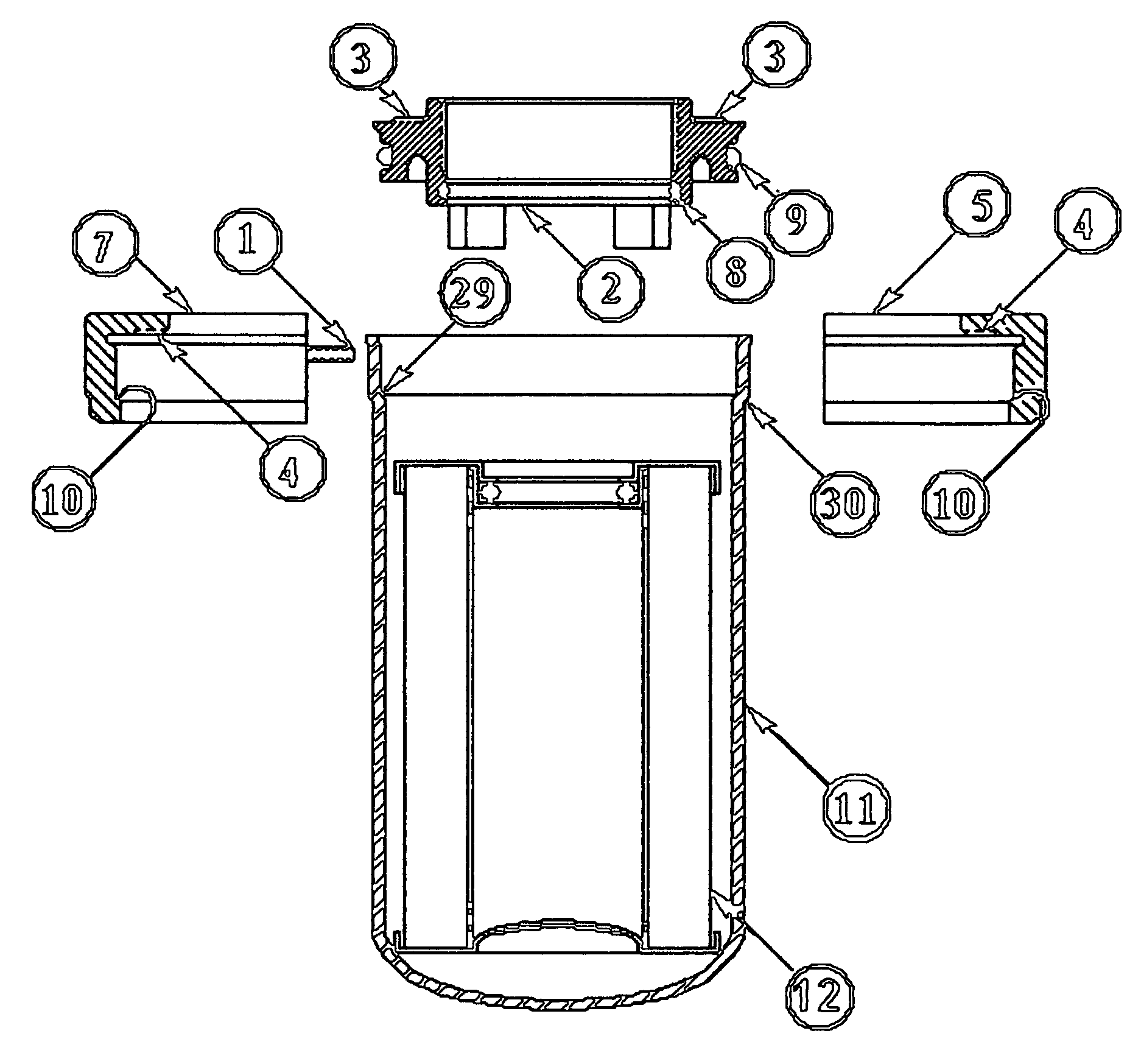
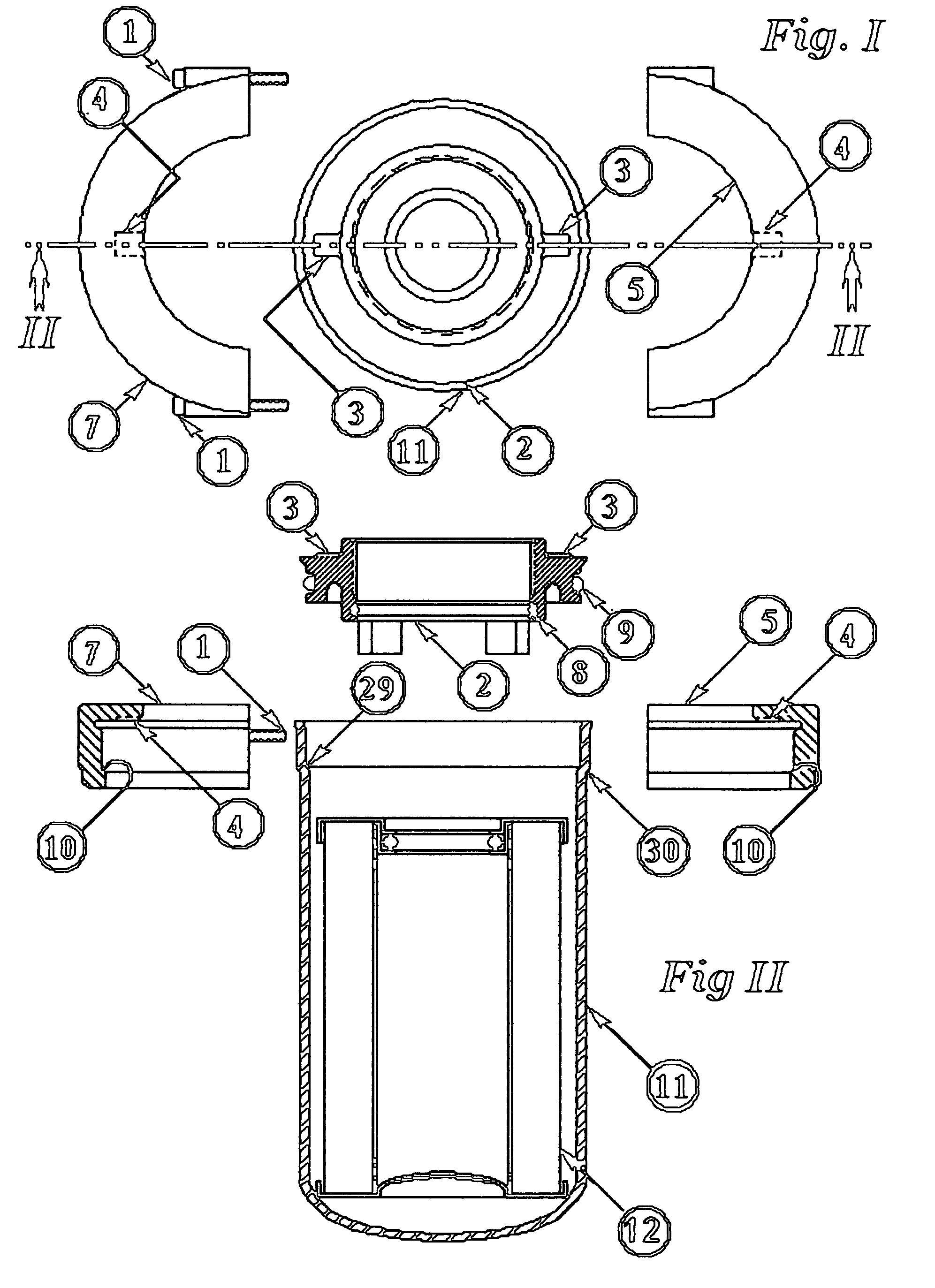
[0010] In order to secure the plate against the hydraulic burst forces, a ring in two 180 degree halves mate to form a 360 degree ring, which mating simultaneously engages beneath the shoulder formed by the expanded open end of the shell and, by virtue of the “L” section of the rings, extends as a rim which overlaps the plate. Bolts are used to secure the ring halves to the strength equivalent to a continuous ring structure. Thus, the separable ring halves are what enables the plate, and then the inner element, to be separated from the shell without damage to plate or shell. With a new element reinserted, the original metal parts (or spare parts) are used to complete the assembly with a new filter element. The refurbishing is preferably done away from the machine where it functioned, and the unit can be stocked as a replacement part, thus effecting the safest method of re-attaching; i.e. which is the same procedure as used with the throw away spin-on at the machine site.
[0012] The re-encapsulation is preferably done away from the machine where it functioned, and there the unit can be stocked as a replacement part, thus effecting the safest method of re-attaching; i.e. the same procedure as used with the throw away spin-on at the machine site. It is obvious that with the general approach taken, a variety of attaching plate profiles can be accomodated, thus enabling the invention to be adapted so as to fit a variety of spin-on attachment profiles.

Problems solved by technology

But, reversion to a traditional, permanent style filter (defined as a block like head and shell / cannister), as an environmental solution, has serious drawbacks which, it can be argued, are: (a) a reversion to an inferior contamination control mechanism; (b) will entail high costs to the general infrastructures to implement, both for filter manufacturers, and for the customers that use the product; (c); will still leave the disposal of the oil and the spent element as environmental concerns; and (d); will mean the use of large attaching threads between shell and head in order to allow for element serviving, thus deriving an unnecesarily large head mass.

Method used


Image

  • Re-usable structure which attaches to the same filter head as originally intended to receive a throw-away spin-on
  • Re-usable structure which attaches to the same filter head as originally intended to receive a throw-away spin-on
  • Re-usable structure which attaches to the same filter head as originally intended to receive a throw-away spin-on

Examples


Embodiment Construction

[0027] FIG. I represents the exploded, top view of the invention, either ready for removal of a spent element (12), or ready for re-assembly after insertion of a new element (12). Loose screws (1) will clamp the ring halves (5) and (7) into a 360 degree effective ring at the the completed assembly. Plate (2) and shell (11) are shown concentrically. Section II-II is the elevation section through the exploded view.

[0028]FIG. 11 represents Sec II-II, in FIG. I, in an elevation view.

[0029] One particular choice of plate casting, item (2), is preferably made of an aluminum die casting, and its constant features are the keys (3), o-ring seal (9), and the outer portion of plate which nests in the assembled position into the mouth of the shell (11). Seal (8) is a second o-ring radial seal which may be required to adapt to one common filter head. The corner (29) of shell (11) provides the positioning means for the plate (9). Rubber o-ring (9)

[0030] effects a radial piston seal with shell ...


PUM

PropertyMeasurementUnit
Angleaaaaaaaaaa
Angleaaaaaaaaaa
Thicknessaaaaaaaaaa

Abstract

A re-usable, spin-on filter cannister for hydraulic use, which can attach to a block-like head; said head being previously existent for attachment of a conventional, throw-way, spin-on type cannister. The invention is designed with metal parts which can be assembled or dis-assembled without damage. Thus, when the spent filter element is discarded, the housing parts can be reused with a fresh element, without physical alteration to any of the metal container parts. The assembly / dis-assembly mode, which enables reuse, is by means of a radial displacement of split rings which, in engagement with the cannister and plate, act to contain the hydraulic stresses within the filter assembly.

Description

CROSS REFERENCE TO RELATED APPLICATIONS [0001] (not applicable) STATEMENT REGARDING FEDERALLY SPONSORED RESEARCH OR DEVELOPMENT [0002] (not applicable) REFERENCE TO A “SEQUENTIAL LISTING”[0003] (not applicable) BACKGROUND OF THE INVENTION [0004] The use of the spin-on can format, a system whereby a filter element is packaged within a lightweight steel container, and that container not being reusable for replacing with a fresh element, has been both the dominant economic choice, and importantly, the one whereby contamination control is better achieved during the servicing operation. [0005] In general, these throw-away designs have, at the attaching end, a plate structure with features defining an internal threading means, and a seal(s) arrangement defining inlet and outlet hydraulic flows in order to mate with a permanent, block head structure, from which head structure the fluid arrives and to where it exits after filtration. [0006] Various schemes to seal the plate structure to the...

Claims


Application Information

Patent Timeline
IPC IPC(8): B01D27/08B01D35/30
CPCB01D27/08B01D2201/302B01D35/30
Inventor STIFELMAN, JACK
Owner STIFELMAN JACK
Learn More