Electrical penetrator assembly

Inactive Publication Date: 2020-01-09
VETCO GRAY SCANDINAVIA
View PDF3 Cites 0 Cited by
  • Summary
  • Abstract
  • Description
  • Claims
  • Application Information

AI Technical Summary

Benefits of technology

The present invention provides an electrical penetrator assembly that allows for the use of higher rating insulation materials, which is important for certain applications such as rotating machinery. The assembly is compact, lightweight, and cost-effective. It also has a limited number of penetrations through the pressure housing, which increases the mechanical capacity of the unit.

Problems solved by technology

Devices for conducting electrical power through the housing wall can thus be subjected to considerable axial forces resulting from the pressure difference between the surrounding sea and the fluid filled housing.

Method used


Image

  • Electrical penetrator assembly
  • Electrical penetrator assembly
  • Electrical penetrator assembly

Examples


first embodiment

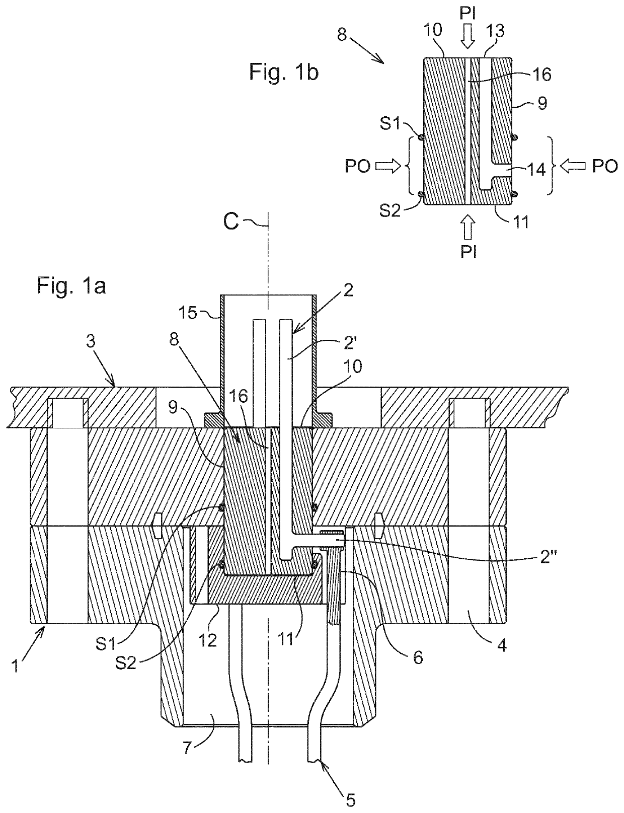
[0040]Thus, with reference to FIGS. 1a and 1b the electrical penetrator assembly comprises a penetrator housing 1 in which one or more conductors 2 extend in a first direction for connecting with an electrical appliance (not shown) inside a housing 3. The penetrator housing 1 of the shown embodiment is a rotation symmetric assembly, in the art also referred to as a flange, with holes 4 for bolting the penetrator 1 to the wall of the housing 3. In mounted position, the penetrator assembly forms a part of the barrier that separates the inside environment from the outside environment, e.g. having different pressures or fluid content.

[0041]The conductor 2, capable of conducting electrical power extending from a first end of the penetrator housing, is made in a conductive material such as cupper or aluminium e.g., and is dimensioned for conducting electrical power at high ratings (high voltage, high current) to the electrical appliance inside the housing 3. Electrical power is supplied t...

third embodiment

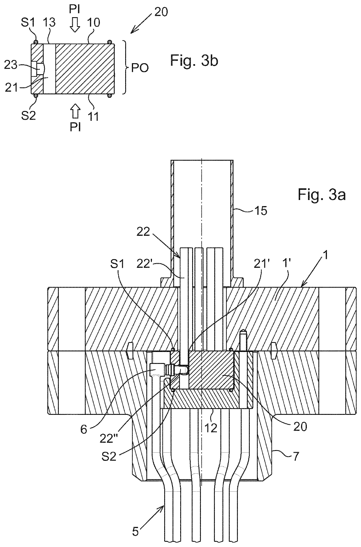
[0054]the electrical penetrator assembly is illustrated in FIG. 3. The embodiment of FIG. 3 differs from the embodiment of FIG. 2 with respect to the arrangement of the insulator body 20 in the penetrator housing. More particularly, in the embodiment of FIG. 3 the insulator body 20 is axially secured between the seat 12 and housing component 1′, by engagement from a section of housing component 1′ which bears on the first end face 10 of the insulator body. Similar to previous embodiments, the second end face 11 is accommodated in the seat 12.

[0055]In this third embodiment, the sealing systems S1 and S2 are arranged at the end faces 10, 11 for sealing against the penetrator housing. These seals S1 and S2 of the third embodiment can be realized as rings, biased in the axial direction.

[0056]As in the first and second embodiments, the external pressure PO is restricted to act on the insulator body 20 exclusively between the seals S1 and S2. Internal pressure PI is routed via the clearan...

fourth embodiment

[0058]FIG. 4 illustrates the electrical penetrator. The embodiment of FIG. 4 comprises a conductor 2 including an axial conductor member 2′ adjoining a radial conductor member 2″. The axial conductor member 2′ is accommodated in a tube-shaped insulator body 30 forming a sleeve around a portion of the axial conductor member 2′. A longitudinal bore 31 through the axial conductor member 2′ leads internal pressure PI to the second end of the conductor member 2′. An insulator disc 32 is inserted in the seat 12.

[0059]In correspondence with the previous embodiments, the radial conductor member 2″ exits the insulator body 30 via a laterally facing opening 33 between sealing systems S1 and S2, respectively. More particularly, sealing system S1 comprises an outer sealing ring 34 sealing between the outside of the sleeve-shaped insulator body 30 and the penetrator housing, and an inner sealing ring 35 sealing between the inside of the insulator sleeve and the axial conductor member 2′. In corr...


PUM


Abstract

An electrical penetrator assembly comprising a penetrator housing (1), at least one conductor (2; 22) capable of conducting electrical power extending from a first end of the penetrator housing, an insulator body (8; 20; 30) surrounding the conductor, wherein the conductor passes through the insulator body from an axially facing opening (13) in a first end of the insulator body to a laterally facing opening (14; 23; 33) in the side of the insulator body, the laterally facing opening (14; 23; 33) located in a section PO of the insulator body which is sealed (S1; S2) towards the penetrator housing on each side of the lateral opening.

Description

TECHNICAL FIELD OF THE INVENTION[0001]The present invention relates to a penetrator assembly arranged for conducting electrical power to an electrical appliance that is shielded from the external environment by means of a housing or vessel creating a fluid and pressure barrier around the apparatus.BACKGROUND AND PRIOR ART[0002]In subsea applications, e.g., pump or compressor motors, switchgear, transformers and other electrical appliances may be supplied electrical power via an opening in a wall of a housing that protects the inboard apparatuses from water outside the housing. The housing is typically filled with fluid, gas or oil, for electrically insulating and / or cooling purposes. At water depth down to 1,000 m and beyond, and at production pressure of 100-300 bar or more, the pressure difference over the housing wall may be considerable. Devices for conducting electrical power through the housing wall can thus be subjected to considerable axial forces resulting from the pressure...

Claims


Application Information

Patent Timeline
IPC IPC(8): H02G3/22H01R13/523H01R13/52H02G15/14
CPCH02G15/14H01R13/5202H01R13/523H02G3/22H01R13/405H01B17/26H01B17/301H01B17/303
Inventor RAAD, ERIKELNAN-KUNTSEN, JAN ERIK
Owner VETCO GRAY SCANDINAVIA
Why Eureka
Try Eureka