Screw jack for structures for easily adjusting its angle

a technology of screw jack and structure, which is applied in the field of screw jack, can solve the problems of limiting the usefulness of the screw jack to provide bracing or other angular support to excavated earthen or structural steel shapes, difficult task to perform quickly and accurately, and time-consuming and unwelcome tasks, so as to reduce the number of working processes, facilitate the adjustment, and enhance the effect of working efficiency

Inactive Publication Date: 2006-02-02
HANYOU CORP
View PDF7 Cites 7 Cited by
  • Summary
  • Abstract
  • Description
  • Claims
  • Application Information

AI Technical Summary

Benefits of technology

[0006] Therefore, the present invention has made in view of the above problems, and it is an object of the present invention to provide a screw jack for structures which is capable of adjusting a chute member located at one end of the screw jack such that angles of the screw jack to be installed to vertica

Problems solved by technology

Consequently, the angle of inclination is fixed, which, in turn, limits the usefulness of the screw jack to provide bracing, or other angular support to excavated earthen or structural steel shapes, at anything other than a predetermined angle.
Depending on conditions at the construction site however, this is a difficult task to perf

Method used


Image

  • Screw jack for structures for easily adjusting its angle
  • Screw jack for structures for easily adjusting its angle
  • Screw jack for structures for easily adjusting its angle

Examples


second embodiment

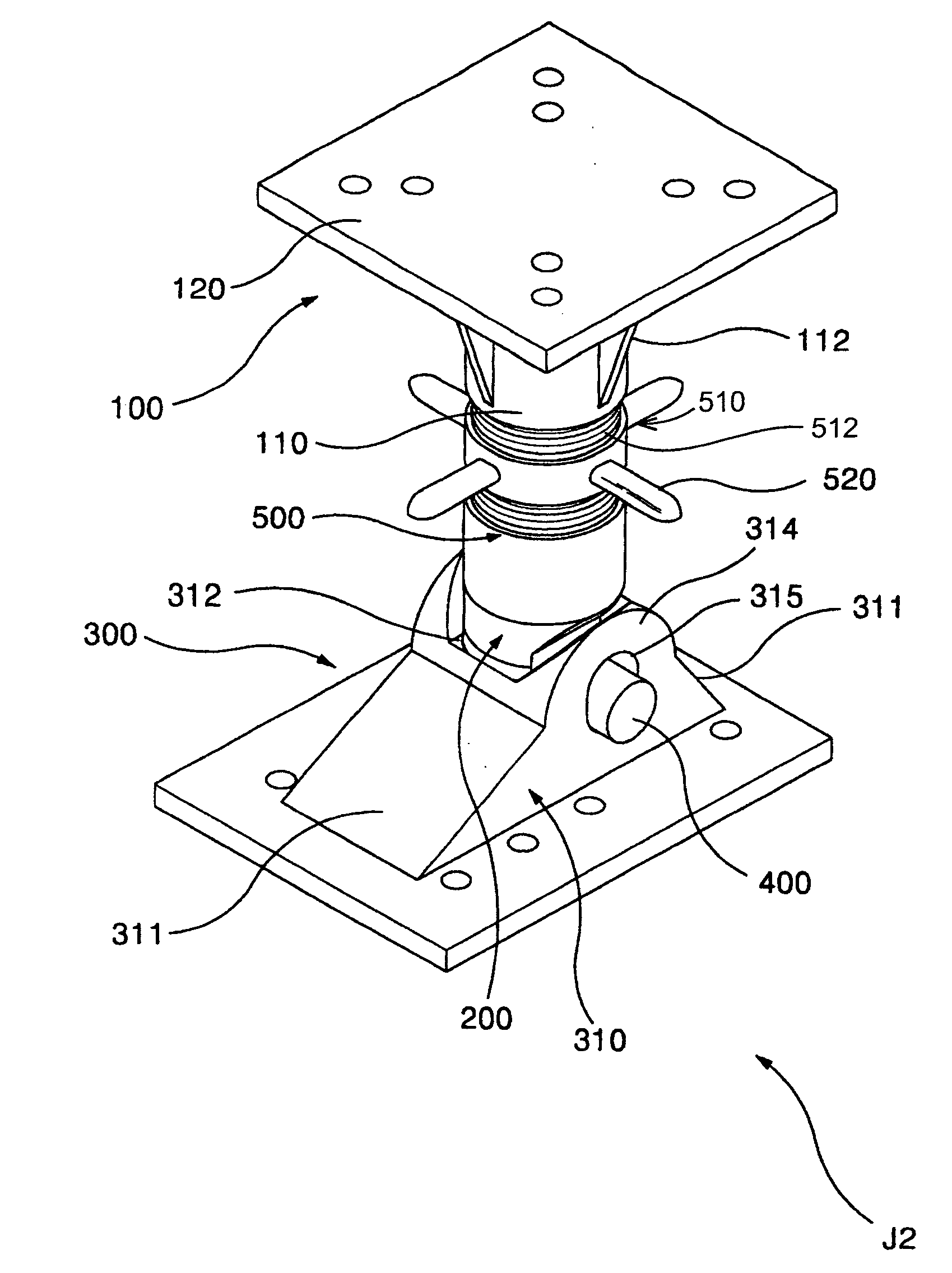
[0041]FIGS.9, 10, 11, 12 and13 collectively provide perspective and elevation views illustrating a structural screw jack capable of easily accommodating adjustment of its angle of inclination, constructed as the present invention.

[0042] As shown in FIGS.9 through 13, screw jack J2, when constructed as a second embodiment of the present invention has the same overall as the configuration of screw jack J1 in accordance with the first embodiment of the present invention, as shown in FIGS. 5 to 8. More specifically, screw jack J2 is constructed with an upper jack 100, a lower coupling shaft 200, a lower jack 300, and a steel pin 400.

[0043] Upper jack 100 may be constructed with upper coupling pipe 110 having a plurality of reinforcing ribs 112 formed on the outer side surface thereof, and an upper holder 120 closely coupled to the outer side surface of upper coupling pipe 110. Upper holder 120 may be shaped as a plate.

[0044] Lower coupling shaft 200 maybe shaped as a bar. One end of l...


PUM


Abstract

A structural screw jack capable of easily accommodating adjustment of its angle of inclination. The screw jack can allow the orientation of a chute located at one end of the screw jack is be adjusted to define either a right angle to the longitudinal axis of the jack, or over a range of oblique angles relative to its longitudinal axis so that the screw jack may be installed at an oblique angle between earlier installed vertical and horizontal oriented structural steel shapes, and thereby enabling a reduction in the number of process steps customarily used during field installation of diagonal braces supported by a screw jack. The screw jack includes a lower coupling shaft, a lower jack, and a steel bar. The upper jack includes an upper coupling pipe having a plurality of reinforcing ribs formed on the outer side surface thereof, and an upper holder closely coupled to the outer side surface of the upper coupling. One end of the lower coupling shaft is integrated at its one end to the lower portion of the upper coupling pipe. The other end of the lower coupling shaft having a predetermined curvature forming a rack thereon and has a through hole formed in the cross direction of the lower coupling shaft. The lower jack includes a chute in which pinions are formed to be meshed with the rack, and coupling holes located at both sides of the chute member are formed. A lower holder which is closely coupled to the outer surface of the chute.

Description

CLAIM OF PRIORITY [0001] This application makes reference to, incorporates the same herein, and claims all benefits accruing under 35 U.S.C.§119 from an application for SCREW JACK FOR STRUCTURES FOR EASILY ADJUSTING ITS ANGLE earlier filed in the Korean Intellectual Property Office on the 28 Jul. 2004, and there duly assigned Serial No. KR2004-59171. BACKGROUND OF THE INVENTION 1. Field of the Invention [0002] The present invention relates to a screw jack capable of easily adjusting its angle of inclination relative to a structure being supported, and, more particularly, to a screw jack for structures which is capable of easily adjusting a chute member located at one end of the screw jack, to enable the screw jack to be readily and accurately adjustably installed obliquely against vertical and horizontal steel structural shapes. [0003] 2. Description of the Related Art [0004] Generally, screw jacks such as have been disclosed in Korean Utility Model Application No. 20-1999-3277, fil...

Claims


Application Information

Patent Timeline
IPC IPC(8): B66F3/08E02D17/04E02D17/08
CPCE02D17/083E02D17/04E02D2200/1671E02D2600/20E02D2600/40
Inventor OH, SANG-HWAN
Owner HANYOU CORP
Why Eureka
Try Eureka