
Wheel end steering sensor system

a sensor system and steering wheel technology, applied in the field of sensors, can solve the problems of increasing the number of converters, increasing the number of parts, and affecting the computation of wheel angle,

Inactive Publication Date: 2006-02-02
STEERING SOLUTIONS IP HLDG +1
View PDF7 Cites 48 Cited by
  • Summary
  • Abstract
  • Description
  • Claims
  • Application Information

AI Technical Summary

Benefits of technology

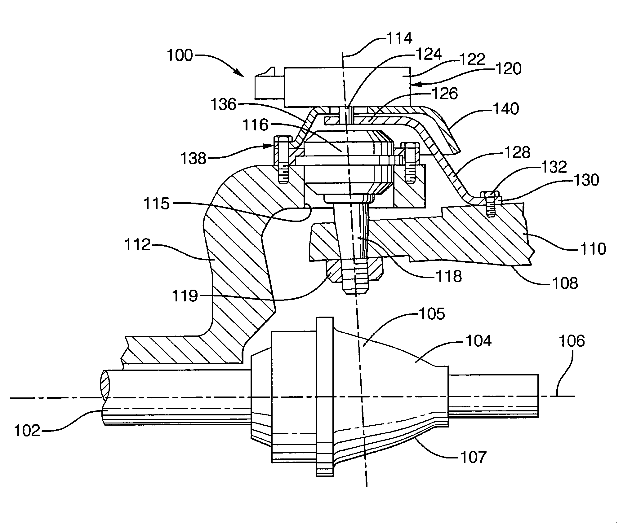
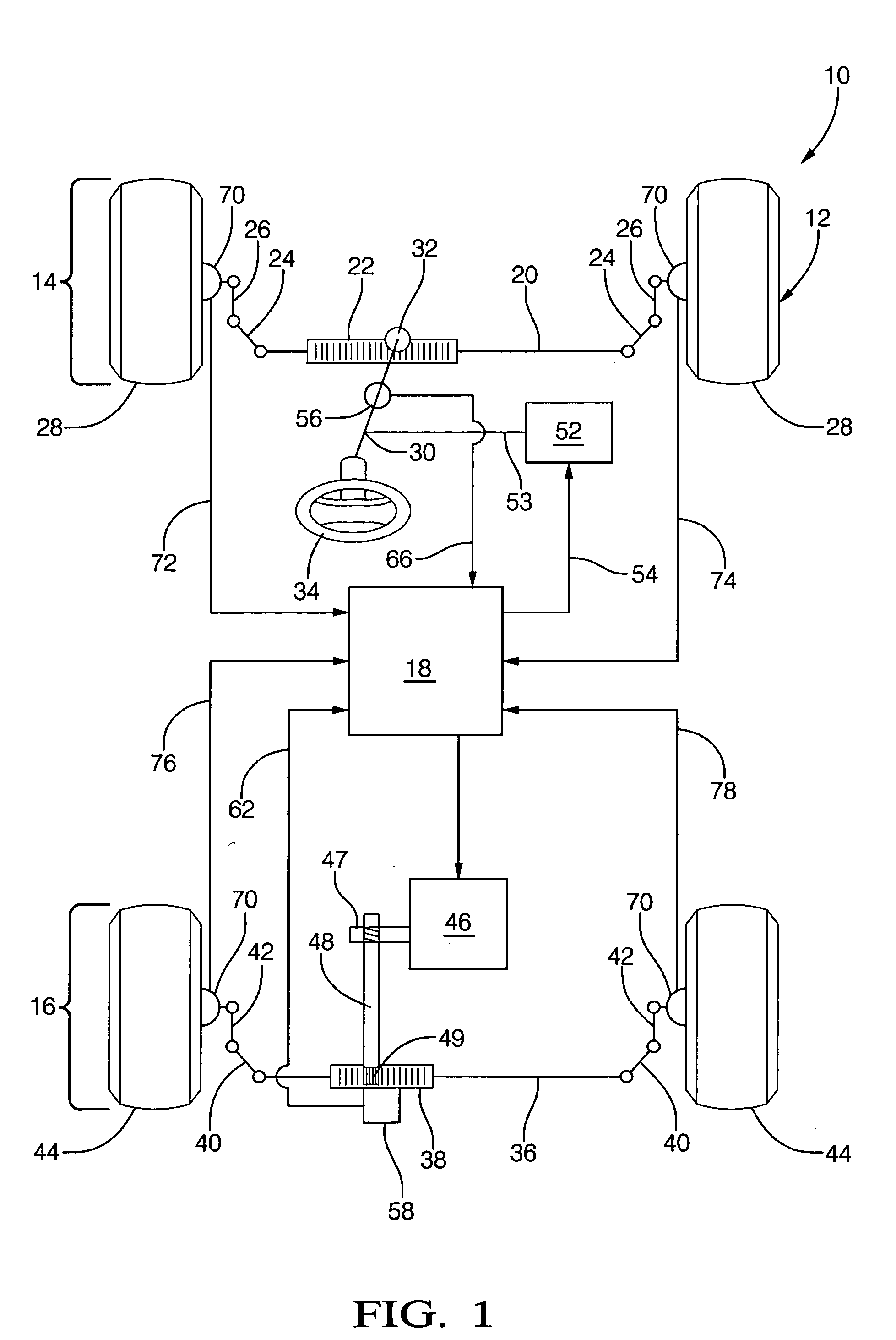
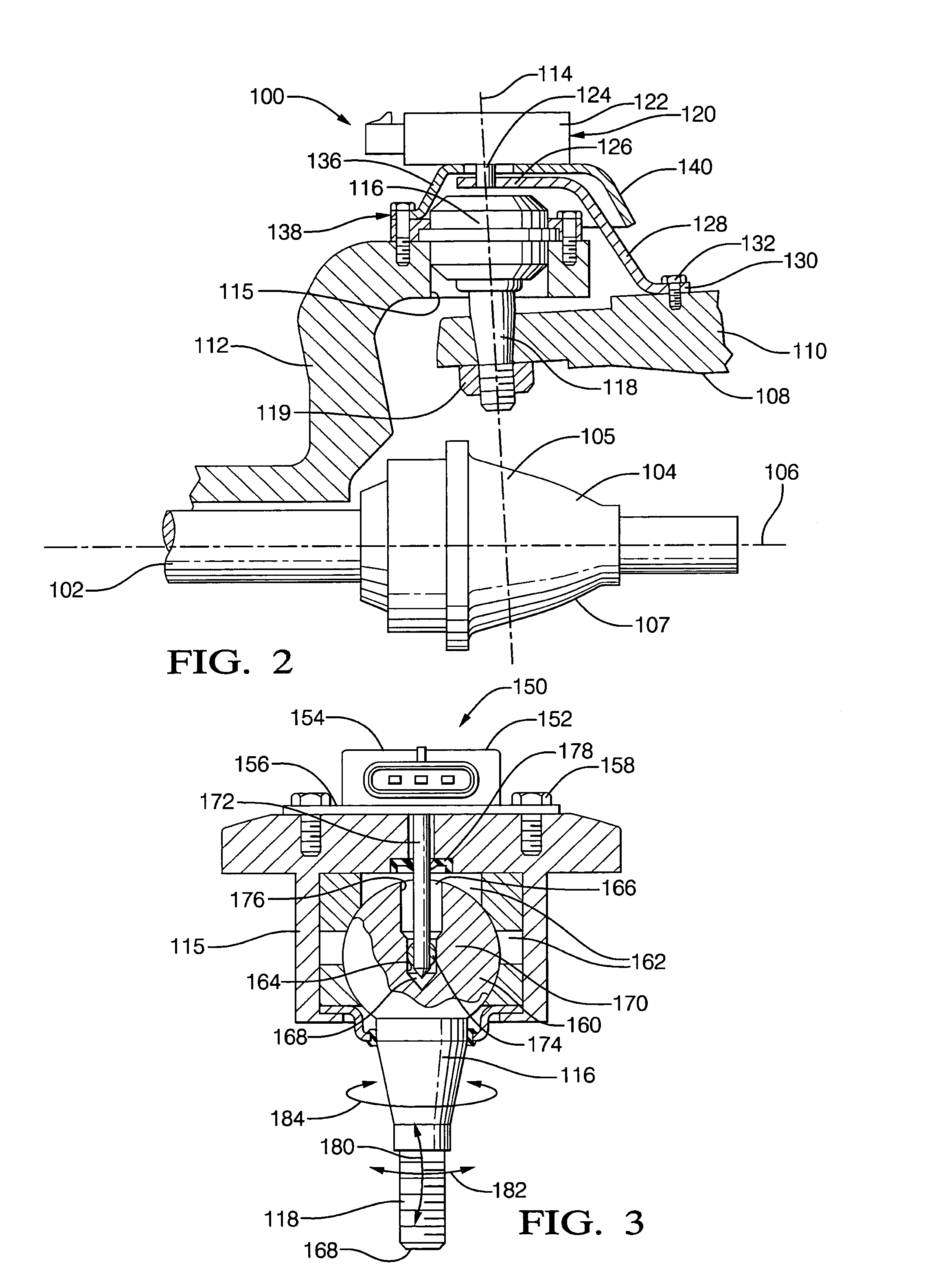
[0007] Disclosed herein, in an exemplary embodiment, is a steerable element angular sensor system including a sensor having a sensing axis, the sensing axis positioned along an axis of rotation of a knuckle, a connector connecting a yoke and the knuckle of a steering system. The sensor detects rotation of at least one of the knuckle and the connector and the sensor system includes protection from rotation detection interference from linear and angular movements of at least one of the connector and the knuckle.
[0008] Also disclosed herein, in another exemplary embodiment, is a steerable element assembly including a first housing element including a steering knuckle movable in response to a steering system, a second housing element, a connector connecting the steering knuckle to the second housing element, and a sensor having a sensing axis, the sensing axis positioned along an axis of rotation of the knuckle. The sensor detects rotation of at least one of the knuckle and the connector and the sensor system includes protection from rotation detection interference from linear and angular movements of at least one of the connector and the knuckle.

Problems solved by technology

The moving amount of the piston rods is detected by a stroke sensor, which is expensive.
The angle of the wheels is computed based on the value detected by the stroke sensor, which complicates the computation of the wheel angle.
The use of a converter increases the number of parts and complicates the installation of the apparatus.
If the converter is not assembled accurately, the detection of the wheel angle will be inaccurate.
In one example, the sensor is positioned at the bottom of the actuator and additional costs are associated with protecting the sensor from ground clearance and jacking issues.
One problem with measuring a steered wheel angle is that the wheels and the steered wheel axis are potentially subject to harsh environmental conditions.
This makes locating measurement systems or sensors difficult.
Environmental conditions such as dirt or water can adversely impact the accuracy of sensor measurements or damage sensors.
Prior wheel angle sensors, which are located so as to be protected from environmental damage, have been difficult to reach for maintenance and repair purposes.

Method used


Image

  • Wheel end steering sensor system
  • Wheel end steering sensor system
  • Wheel end steering sensor system

Examples


Embodiment Construction

[0015] The wheel angle sensors and mounts disclosed herein may sense the position of the wheel end directly. Placing a sensor at each wheel end adds a layer of diagnostics to the overall system by allowing the controller(s) to know the angle of the wheel regardless of the state of health of the tie rods, tie rod ends, rack or anything else that is between the sensor and the wheel end. This may be best accomplished with one sensor at each wheel end. A side benefit of having a sensor at each wheel end is true redundancy of the sensor signal. In addition, the position at the wheel end increases accuracy by eliminating the lash and compliance of components that are bypassed.

[0016] The wheel angle sensor may be a rotary type of any suitable technology (i.e. contacting, non-contacting) for a particular application. Rotary sensors may be designed to convert rotary motion into an electrical signal. A linear output voltage is directly proportional to the angle of rotation of the sensor. Alt...


PUM


Abstract

A steerable element angular sensor system may include a sensor having a sensing axis positioned along an axis of rotation of a knuckle, a connector connecting a yoke and a knuckle of a steering system. The sensor may detect rotation of at least one of the knuckle and the connector. Also, the sensor system may include protection from rotation detection interference from linear and angular movements of at least one of the connector and the knuckle. The sensor system may be included within a steerable element assembly and provided within a vehicle.

Description

BACKGROUND [0001] This invention relates generally to sensors usable in vehicular applications, and more particularly, this invention relates to a steerable wheel angle sensor and mount. [0002] Wheel angle signals from a wheel angle sensor may be employed by electronic data management to fine-tune power steering parameters, making driving easier and more enjoyable. In some vehicles, the wheels may be independently supported and steerable, and it may be necessary to have coordinated steering angles between front and rear wheels. Computer controls are able to resolve signals indicating steer angle differences, and make adjustments to the steering system as necessary, or, alternatively, provide different angles of certain wheels for various purposes. [0003] In one prior system of measuring wheel angle in a vehicle, a power steering apparatus is provided with a steering shaft, which is rotated by manipulation of a steering wheel, and a valve unit coupled to the steering shaft. The valve...

Claims


Application Information

Patent Timeline
Patent Type & Authority Applications(United States)
IPC IPC(8): B60P1/00B60G1/00
CPCB62D15/023
Inventor PRESSLER, JOHN F.LEMANSKI, BRIAN D.RICHARDSON, GORDON D.RUPPERT, MALCOLM F. JR.
Owner STEERING SOLUTIONS IP HLDG
Learn More