Annular sensor housing

a sensor housing and annular technology, applied in the direction of linear/angular speed measurement, instruments, devices using electric/magnetic means, etc., can solve the problems of inability to use the sensor housing to seal the bore of machine parts, inaccurate positioning of the angle of the ring, etc., to achieve low installation space requirement, high signal quality, and low manufacturing cost

Inactive Publication Date: 2006-02-02
CARL FREUDENBERG KG
View PDF12 Cites 6 Cited by
  • Summary
  • Abstract
  • Description
  • Claims
  • Application Information

AI Technical Summary

Benefits of technology

[0010] Starting from this prior art, an object of the present invention is to provide a sensor housing which is inexpensive to manufacture, which can be installed without complex alignment procedures, has a small installation space requirement, and ensures a rigid support of the sensor. This, in turn, results in a high signal quality since the housing according to the present invention does not permit any misalignment with respect to the shaft, as a result of which a misalignment of the sensor can easily be avoided.

Problems solved by technology

In this context, it is a disadvantage that the positioning of the angle of the ring can be carried out only inaccurately.
In the known designs, the sensor housings cannot be used to seal bores in machine parts, that is, they do not encircle the shaft on its circumference in a centered manner.

Method used


Image

  • Annular sensor housing
  • Annular sensor housing
  • Annular sensor housing

Examples


Embodiment Construction

[0050] The following description of the preferred embodiment(s) is merely exemplary in nature and is in no way intended to limit the invention, its application, or uses.

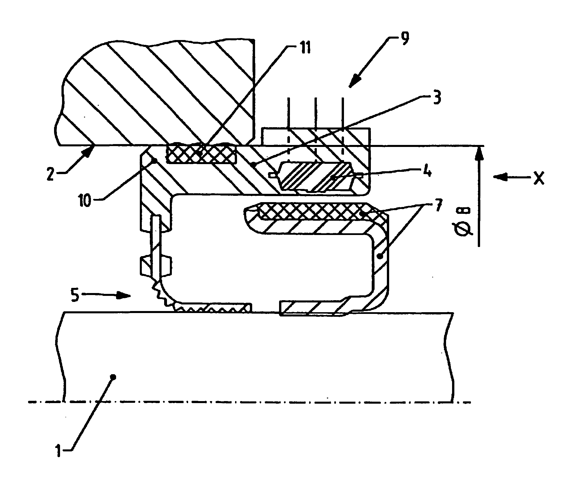
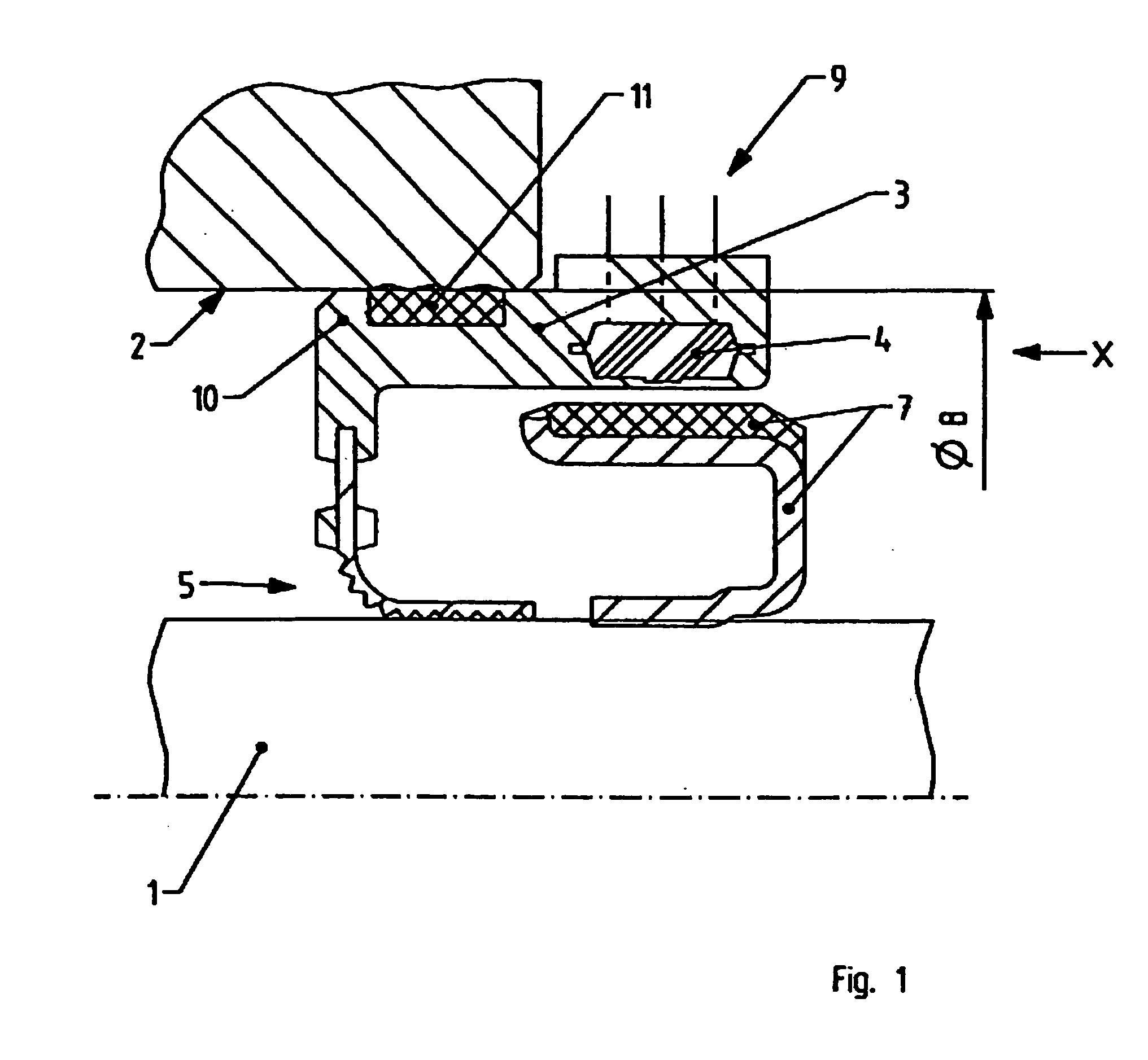
[0051]FIG. 1 shows an embodiment of the sensor device according to the present invention in a longitudinal cross-section. An encoder wheel 7 is nonrotatably connected to shaft 1. Shaft 1 is passed through a central bore of annular sensor housing 3 to the outside. Sensor housing 3 has an adhesion part 10 of a shaft sealing ring 5 which provides the dynamic sealing of shaft 1 and the static sealing of a receiving bore 2. Adhesion part 10 of shaft sealing ring 5 is preferably formed of plastic, for example, of a thermoplastic or thermosetting plastic. In the embodiment shown, adhesion part 10 and sensor housing 3 are integrally formed of the same material. Sensor housing 3 is designed such that a narrow gap is formed between encoder wheel 7 and the sensor housing 3. Located in sensor housing 3 is at least one sensor 4 ...


PUM


Abstract

A sensor device for a shaft of a machine having a machine housing, the shaft having a shaft circumference and the machine housing having a sealed receiving bore. The sensor device includes a sensor for measuring motion parameters of the shaft and a stationary annular sensor housing that supports the sensor and encircles the shaft about the shaft circumference in a centered manner and at a distance. The sensor housing is retained in the receiving bore by a press fit or screw connection.

Description

CROSS-REFERENCE TO RELATED APPLICATIONS [0001] This application is a divisional of U.S. patent application Ser. No. 10 / 350,683, filed on Jan. 24, 2003 (now U.S. Publication No. 2004 / 0145365A1). This application relates to German Patent Application No. 10149642.7-52, filed Oct. 9, 2001. The disclosures of the above applications are incorporated herein by reference in their entirety.BACKGROUND OF THE INVENTION [0002] The present invention relates to an annular sensor housing for tracking the motion of a rotatable shaft. [0003] Housings for receiving sensors which can be used to track the rotation of shafts are known per se. [0004] A sealing flange for sealing rotating machine parts is known from German Utility Model Patent No. DE-U-200 00 694. This sealing flange features a sensor which is secured using spring elements. [0005] German Patent Application No. DE-A-199 22 215 describes a device which allows a sensor to be aligned in a housing. [0006] European Patent Application No. EP-A-4...

Claims


Application Information

Patent Timeline
Patent Type & Authority Applications(United States)
IPC IPC(8): G01P3/48G01P3/54G01D5/347G01D11/24G01D11/30
CPCG01D5/34738G01D11/30G01D11/245
Inventor LUTAUD, DOMINIQUEKAMMERER, ERIC
Owner CARL FREUDENBERG KG
Why Eureka
Try Eureka