Apparatus for partial discharge detection of turn to turn insulation in motor

a technology of partial discharge detection and motor, which is applied in the direction of electric winding testing, air break switch, instruments, etc., can solve the problems of inability to directly confirm whether partial discharges have occurred, inability to precisely measure partial discharge characteristics, and inability to precisely measure partial discharges

Active Publication Date: 2006-02-02
HITACHI IND EQUIP SYST CO LTD
View PDF14 Cites 61 Cited by
  • Summary
  • Abstract
  • Description
  • Claims
  • Application Information

AI Technical Summary

Benefits of technology

[0007] However, when the partial discharges between the winding turns were tried to detect while impulse voltages were being applied to the motor by using the conventional method, partial discharges were observed not only at the steep-fronted rising portion of the impulse voltage but also in the decay part of voltage waveform after the peak voltage was ...

Problems solved by technology

It is clear that the conventional method cannot precisely measure the characteristics of the partial discharges between the winding turns of motor since partial discharges are caused at least between the different phases and between the windings and the core.
Thus, the conventional method cannot precisely measure the partial discharges occurring between the winding turns, and hence cannot directly confirm whether partial discharges have occurred between the winding turns when the manufactured motors are driven by the inverter.
In addition, since the partial discharges cannot be confirmed to have occurred between the winding turns of the manufactured motors or not, the prior art needs a countermeasure against that.
On the other hand, any definite tes...

Method used


Image

  • Apparatus for partial discharge detection of turn to turn insulation in motor
  • Apparatus for partial discharge detection of turn to turn insulation in motor
  • Apparatus for partial discharge detection of turn to turn insulation in motor

Examples


embodiment 1

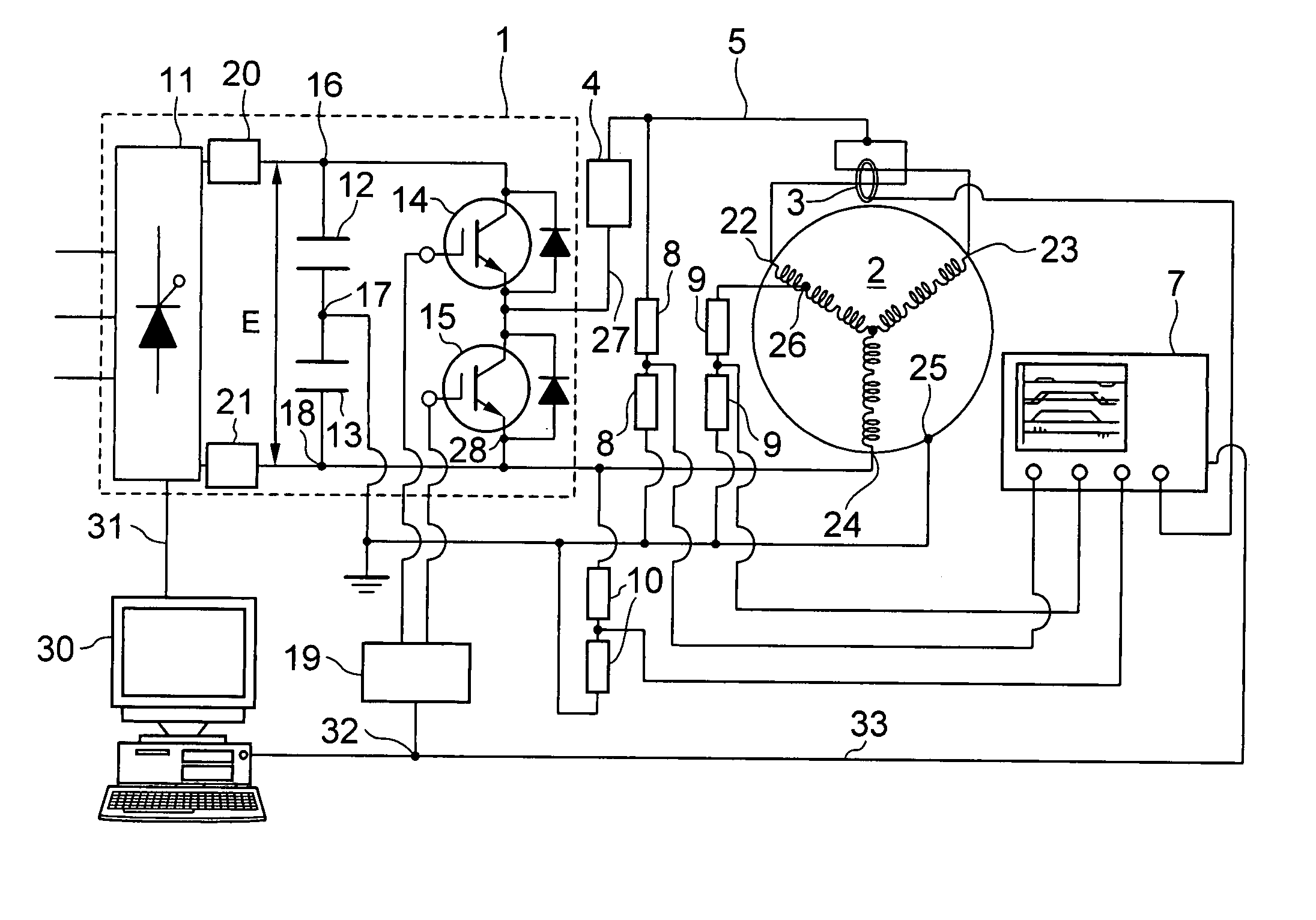
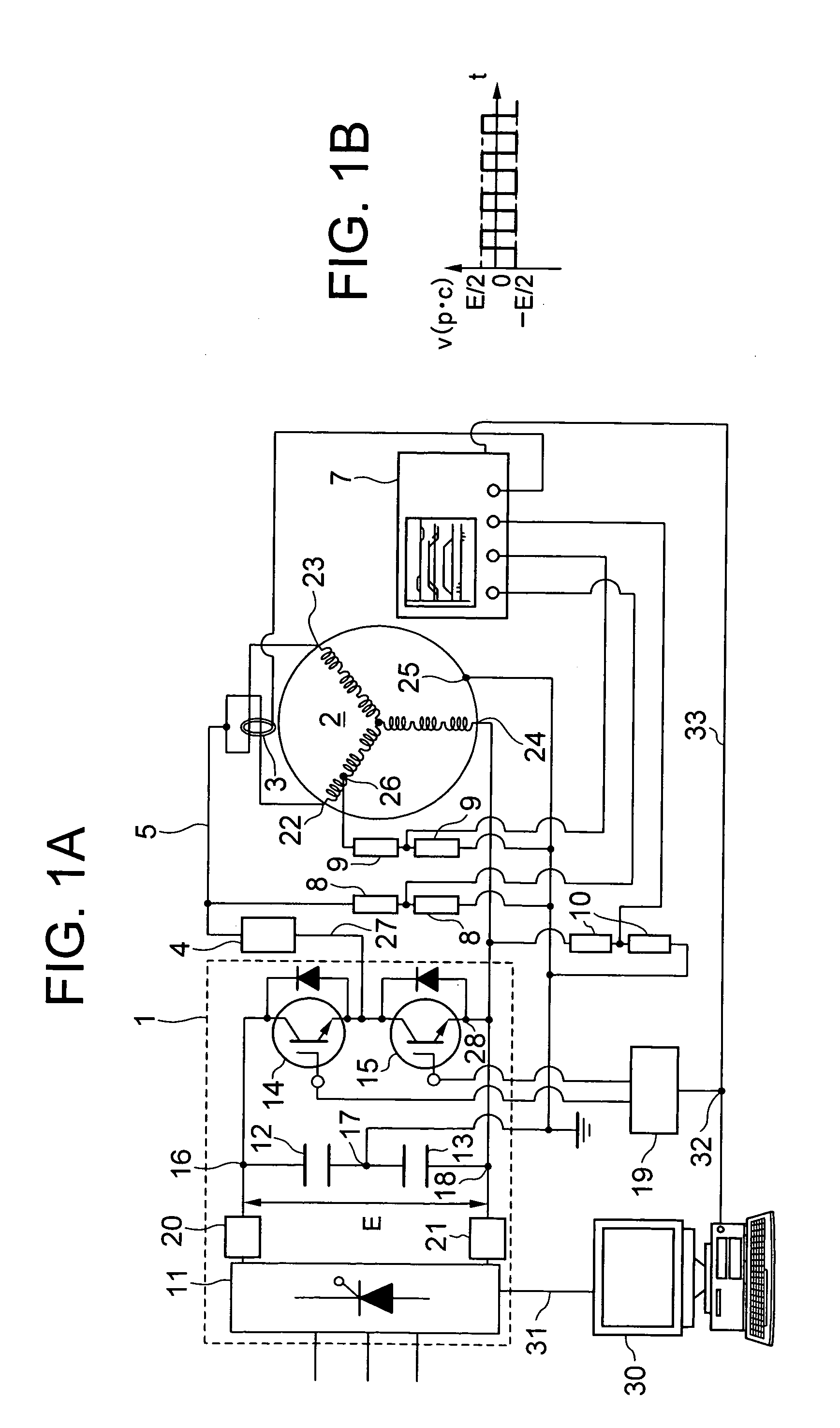
[0051] Embodiments of the invention will be described with reference to the drawings. FIG. 1A shows an apparatus for detecting partial discharges occurring between certain winding turns of a motor, according to the invention. The partial discharge detecting apparatus of this embodiment has a surge generator 1, a surge voltage waveform regulator 4, surge voltage detectors 8, 9, 10, a partial discharge current detector 3, an analyzer / display 7, and a control recorder 30. This partial discharge detecting apparatus detects the partial discharges occurring between certain turns of a winding of a test motor 2. The partial discharges occurring between the certain turns of a winding are, for example, the partial discharges occurring between a lead wire 22 of a winding of the test motor 2 and an arbitrary turn 26 of that winding.

[0052] The surge generator 1 has an AC-to-DC converter 11, smoothing / overcurrent-detecting elements 20 and 21, DC charging capacitors 12 and 13, and switches 14 and ...

embodiment 6

[0107] In the circuit arrangement of embodiment 6, the load resistor 185 equal to the surge impedance of the coaxial cable 182 must be connected to the coaxial cable 182 in order to make the impedance matching. On the opposite side of the coaxial cable to the load resistor, it is necessary to connect the resistor 186 of which the value is larger than the surge impedance of the coaxial cable 182. Since the width of the produced surge is determined by the time lapse in which the surge voltage goes forward and backward on the coaxial cable 182 when the switch 183 is turned on, the pulse width of the surge voltage can be changed by adjusting the length of the coaxial cable 182. In addition, the coaxial cable 182 can be replaced by an LC network circuit.

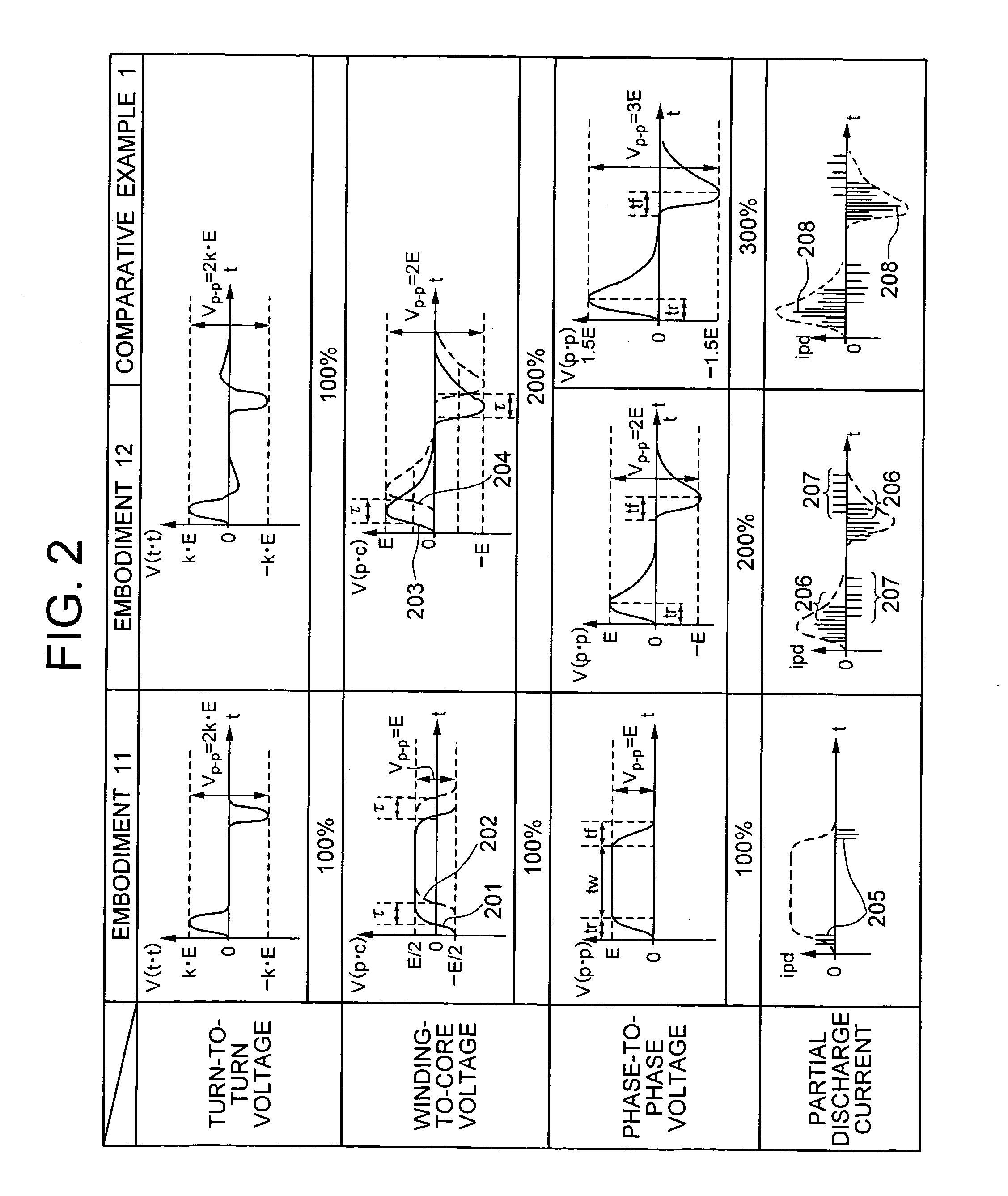
[0108]FIG. 21 shows the waveforms of the turn-to-turn voltage, winding-to-core voltage, phase-to-phase voltage and partial discharge current measured when the partial discharge is caused with the use of the detecting apparatus of the embo...

embodiment 7

[0111] In the circuit arrangement of embodiment 7, the load resistor 2005 equal to the surge impedance of the coaxial cable 2002 must be connected to the coaxial cable 2002 in order to make the impedance matching. On the other hand, it is necessary to open the terminal end, 2004 of the coaxial cable or to connect at the terminal end a resistor that is larger than the surge impedance of the coaxial cable 2002. Since the width of the surge-voltage is determined by the time in which the surge voltage goes forward and backward on the coaxial cable 2002 when the switch 2003 is turned on, the pulse width of the surge voltage can be changed by adjusting the length of the coaxial cable 2002. The coaxial cable 2002 can be replaced by an LC network circuit.

[0112]FIG. 21 shows the waveforms of the turn-to-turn voltage, winding-to-core voltage, phase-to-phase voltage and partial discharge current measured when the partial discharge is caused with the use of the detecting apparatus of the embodi...


PUM

PropertyMeasurementUnit
Timeaaaaaaaaaa
Frequencyaaaaaaaaaa
Frequencyaaaaaaaaaa

Abstract

The apparatus for partial discharge detection of turn-to-turn insulation in motor has a surge generator for generating a surge voltage to the windings of the motor by applying a pulse voltage, and a partial discharge current detector for detecting partial discharge currents between the winding turns of the motor. The surge generator generates in and between the windings of the motor the surge voltage that has the rise time and fall time corresponding to the rise time of the surge voltage observed at the motor terminal when the motor is driven by an inverter, and that is repeated at a frequency of 50 Hz to 20 kHz.

Description

BACKGROUND OF THE INVENTION [0001] The present invention relates to apparatus for detecting partial discharges between the winding turns of motor fed by inverter. [0002] Recently, motors have so far been driven frequently by using inverter so that the motors can be run with adjustable speeds from the standpoint of high-efficient energy consumption and energy conservation. In addition, excellent inverters will be produced and used in the future for many apparatus together with the development of the semiconductor-process and inverter-design and -manufacturing technologies and motor-drive control technology. However, it is feared that the insulating portions of the motors could be deteriorated by the steep-fronted surge voltages that are involved in the motors driven by inverter. Thus, it is necessary to elucidate this phenomenon and study how to cope with that. [0003] This phenomenon of insulation aging is described in detail in, for example, Technical Report No. 739 of Institute of ...

Claims


Application Information

Patent Timeline
IPC IPC(8): H01H31/12G01R31/72
CPCG01R31/1272G01R31/34Y10T29/49004G01R31/06H02K15/105G01R31/346G01R31/72
Inventor OBATA, KOUJIFUKUSHI, KEIJIOBATA, TAKESHISAITO, KOICHIROSHIMOZONO, TADAHIRO
Owner HITACHI IND EQUIP SYST CO LTD
Why Eureka
Try Eureka